From Schematic to Pin Map: Driving PdfCraft, PhotoCraft and VectorCraft from Claude Code over MCP
Three open-source ArtCraft desktop apps expose MCP servers, which lets Claude Code read a schematic PDF, draw a vector pin map from a Zephyr overlay, annotate a board photo and assemble a lab handout. This is a step-by-step guide to the setup and a record of documenting the nRF52840.

Most of the time I spend on an embedded article or a lab handout is not spent on the firmware. It goes on the material around it: finding the right page of a schematic, checking which port pin a header pin connects to, drawing a pin diagram that matches the code, cropping and labelling a board photo, and assembling something a student can print. Each of those is a small job in a desktop application, and none of them is difficult, but they can take time to do properly – diagrams for Exploring Raspberry Pi could take several hours each using Adobe Illustrator.
This article shows my initial attempts at handing those jobs to Claude Code using three open-source desktop apps from the ArtCraft project: PdfCraft, PhotoCraft and VectorCraft. Each one includes an MCP server, which means an AI agent can open files, run the app's commands, render a preview, look at the result and save it, all on my own machine.
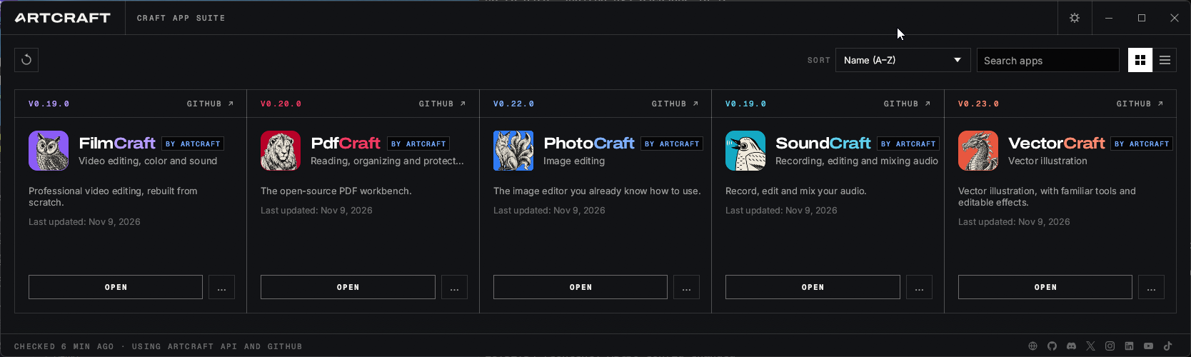
The worked example is the XIAO nRF52840 project from my devicetree article: starting from Seeed's schematic PDF and the project's .overlay file, Claude produced the pin map below, an annotated board photo and a two-page bring-up sheet.
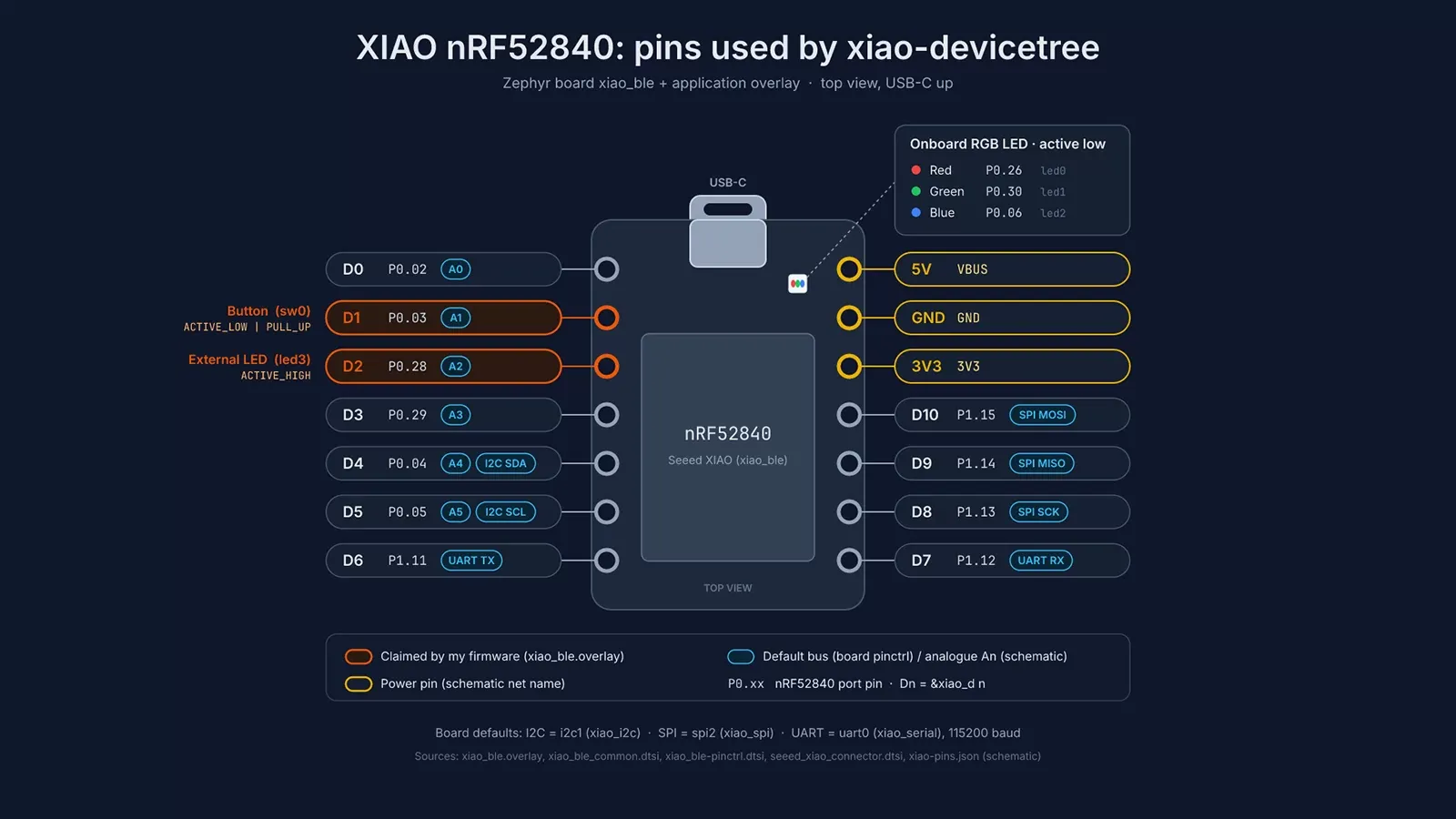
The part I care about most is where the data came from. Nothing on that diagram was typed in by me. The port pins were read from the schematic and cross-checked against Zephyr's own connector file, and the orange highlights come from the overlay the firmware is built with. If I move the button to D3 and run the same prompt again, the diagram changes with it.
C:\zephyr\zephyrproject\xiao-devicetree from the devicetree article. All four stages below were run for real, and the costs, times and failures are the ones I got. Nothing here involves flashing hardware.This is a follow-on to Giving Claude Code a Logic Analyser. That article gave Claude access to the bench instruments, so it could measure what the firmware does. This one gives it access to the desktop tools I use to document the firmware. If you have not used MCP before, the next section has an interactive demo that steps through the messages between Claude Code and PdfCraft, from starting the server to getting a rendered schematic page back.
What MCP adds
The Model Context Protocol (MCP) is an open standard for connecting an AI application to external tools. An MCP server advertises a list of tools, each with a name, a description and a JSON schema for its parameters. The client (Claude Code here) passes that list to the model, and when the model decides to call a tool, the client sends the request to the server and returns the result to the model. The result can be text, JSON or an image.
There are two kinds of MCP server you will come across:
- Remote servers run as a web service. The Google Drive and Slack connectors are examples. Your data goes to that service.
- Local stdio servers run as a child process on your machine. The client starts the program, talks to it over standard input and output, and stops it when the session ends. No network port is opened.
The ArtCraft servers are the second kind. When Claude asks PdfCraft to render page 1 of a schematic, pdfcraft-cli.exe does the rendering on my computer and returns a PNG. The files never leave the machine, although the rendered images and extracted text are sent to the model as part of the conversation, in the same way as anything else Claude Code reads.
The interactive demo below steps through one real exchange: Claude Code starts pdfcraft-cli, asks what tools it has, opens the XIAO schematic and renders page 1. Each step shows the diagram of who sends what to whom, the JSON-RPC messages themselves, and which messages cross from my PC to the Anthropic API. The JSON is what PdfCraft 0.20.0 sent back when I gave it the same requests by hand. The numbered tabs move between the steps, and the full screen button is there for presenting it in a lecture.
Interactive demo: what an MCP server does, one message at a time.
What an MCP server does, one message at a time

The image results are what make this useful for documentation. A tool that only returns text can tell Claude that it drew 57 shapes. A tool that returns a rendered preview lets Claude look at the drawing, see that a label overlaps a pad, and move it. In every stage below, Claude rendered a preview and checked it before exporting, because I asked it to in the prompt.
These are the details:
- The servers run locally. Each MCP server is a child process on your machine. It reads and writes files only inside the folders given by
--automation-read-root and --automation-write-root, and it talks to Claude Code over standard input and output, not over the network. As a spot check, I watched all three CLIs with PowerShell's Get-NetTCPConnection and Get-NetUDPEndpoint during an MCP session (PdfCraft opened and rendered the schematic) and none of them opened a TCP or UDP socket. If you bridge PhotoCraft or VectorCraft to a running desktop app instead of using headless mode, the server talks to the app over a TCP port on 127.0.0.1, which is a loopback connection on the same machine.- The results go to the model. Everything a tool returns becomes part of the conversation, and Claude Code sends the conversation to Anthropic's API. That includes extracted text, rendered page images, JSON, file names and error messages. In this article, the 600 dpi crops of the schematic were sent to the API in the same way as any file Claude Code reads. If you could not paste a document into a chat, do not point an agent at it.
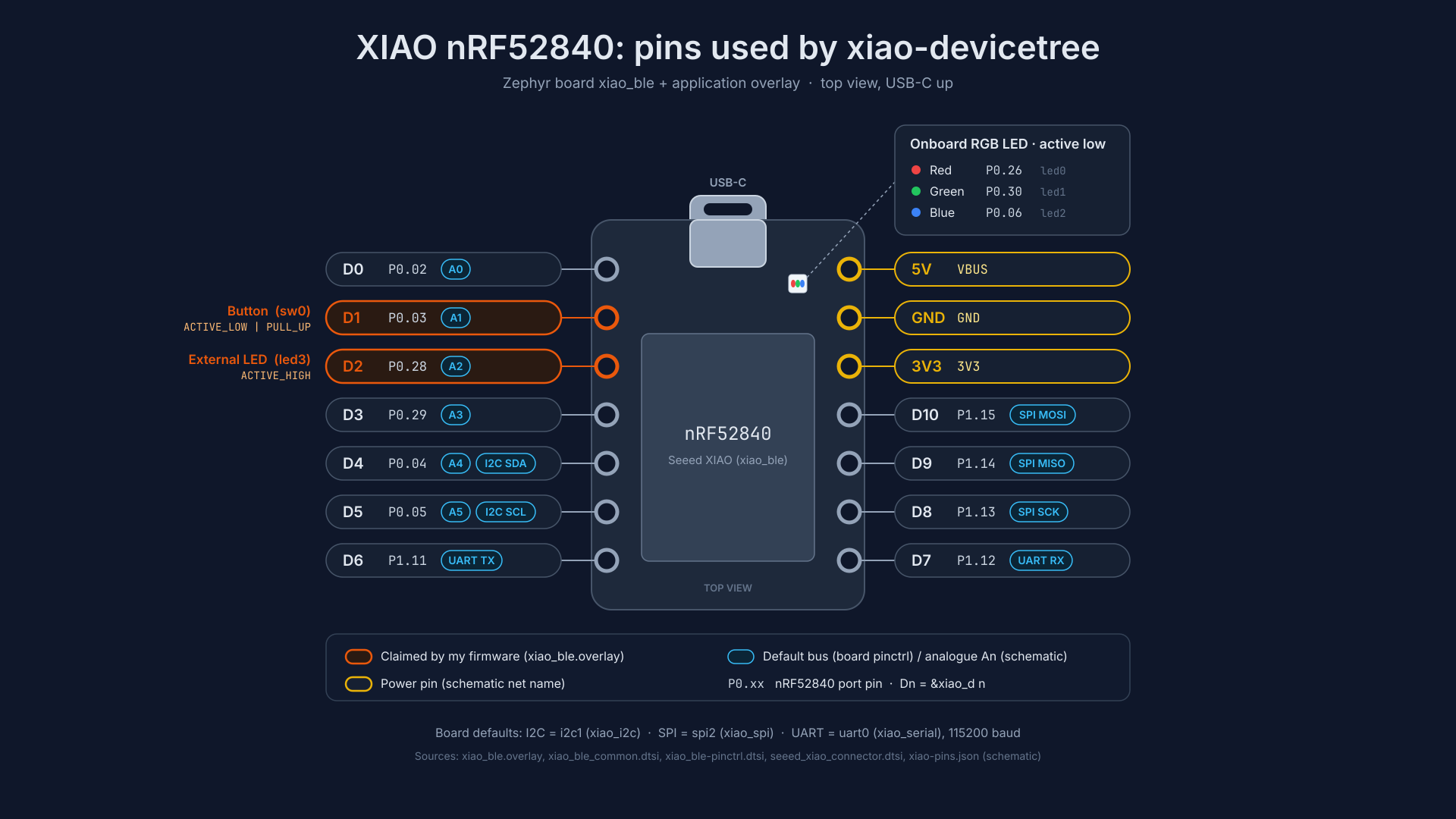
- The launcher is a separate program. The ArtCraft launcher in Figure 1 checks the ArtCraft API and GitHub for updates. It does not need to be running for the MCP servers to work.
- What happens to the data at Anthropic depends on your account. Under commercial terms (Team, Enterprise and the API), Anthropic does not train models on Claude Code data, and the standard retention period is 30 days. On the consumer plans (Free, Pro, Max and Ultra), it depends on the model-improvement setting: with it off, data is kept for 30 days and not used for training; with it on, it can be used for training and is kept for five years. The details are on Anthropic's Claude Code data usage page.
If nothing may leave the machine, the CLIs work without an agent:
pdfcraft-cli run --script, photocraft-cli run and vectorcraft-cli run apply the same tools and commands from a script, with no model involved.If nothing may leave the machine, the CLIs work without an agent: pdfcraft-cli run --script, photocraft-cli run and vectorcraft-cli run apply the same tools and commands from a script, with no model involved.
The ArtCraft apps
ArtCraft describes itself as "Open Source Tools and Models for Makers, Builders, and Creatives". The project is building a set of native desktop apps in Rust (image editing, vector illustration, PDF, video, audio, page layout, CAD and more), all published on GitHub under the storytold organisation. PdfCraft, PhotoCraft and VectorCraft are dual-licensed under the MIT License or the Apache License 2.0, at your option. One of the project's stated principles is that every app can be driven "from a CLI, a JSON control channel or an MCP server, built for automation and AI agents".
I used three of them:
Each app installs two executables: the desktop app (pdfcraft.exe) and a headless command-line version (pdfcraft-cli.exe). The MCP server is a mode of the CLI (pdfcraft-cli mcp), so the desktop app does not need to be open. PhotoCraft and VectorCraft can also bridge to a running desktop app, so you can watch the agent work in the normal window, but I used the headless mode throughout.
The size of the tool lists varies a lot. When I asked Claude to list what it could see, it reported 200 tools for PdfCraft, 26 for PhotoCraft and 33 for VectorCraft. PhotoCraft and VectorCraft keep the list short by exposing a command_list tool and a generic command_run/command_batch that runs any of the app's menu commands by ID. PdfCraft exposes each operation as its own tool. I come back to why that matters in the section on limits.
Step 1: install and register the servers
Install
The ArtCraft Launcher (v0.15.0) installs and updates all the apps, and the app pages recommend it. Each app also has a standalone Windows installer (.msi) and a portable .zip on its page at getartcraft.com/apps/<name>, for example getartcraft.com/apps/pdfcraft. On 10 November the standalone downloads were one release behind the versions I used (PdfCraft 0.19.0, PhotoCraft 0.21.0, VectorCraft 0.22.0), because the launcher picks up new releases first. On my machine the apps are in C:\Program Files\<App>\. The Craft Wiki gives %LOCALAPPDATA%\Programs\ArtCraft\<App>\ as the location for its examples, so check which one you have. Check the CLIs are there:
PS C:\> & "C:\Program Files\PdfCraft\pdfcraft-cli.exe" --version
pdfcraft-cli 0.20.0
PS C:\> & "C:\Program Files\PhotoCraft\photocraft-cli.exe" --version
photocraft-cli 0.22.0 (5000240c6, 2026-11-09)
PS C:\> & "C:\Program Files\VectorCraft\vectorcraft-cli.exe" --version
vectorcraft-cli 0.23.0
Decide which folders the agent can touch
All three servers accept --automation-read-root and --automation-write-root. These confine the files the agent's tools can read and write, and a root that is left out grants no access in that direction. I recommend setting them every time. I used a scratch folder with an in folder for sources and an out folder for results:
C:\Users\Derek Molloy\artcraft-run\
├── in\     schematic PDF, board photo, overlay and dtsi files (read)
├── out\    everything the tools write
└── logs\   prompts and transcripts
The sources were copied into in rather than pointing the tools at my Zephyr workspace. That way the worst a tool call can do is overwrite something in out.
Register the servers with Claude Code
Claude Code finds MCP servers in three places: servers you add with claude mcp add, a file called .mcp.json in the project folder, or a file you name with --mcp-config on the command line. For the runs in this article I used the third, so that each run loaded exactly these three servers and nothing else. This is the file, saved as mcp.json. Forward slashes work for Windows paths in JSON and avoid escaping backslashes:
{
  "mcpServers": {
    "pdfcraft": {
      "command": "C:/Program Files/PdfCraft/pdfcraft-cli.exe",
      "args": ["mcp",
               "--automation-read-root", "C:/Users/Derek Molloy/artcraft-run",
               "--automation-write-root", "C:/Users/Derek Molloy/artcraft-run/out"]
    },
    "photocraft": {
      "command": "C:/Program Files/PhotoCraft/photocraft-cli.exe",
      "args": ["mcp",
               "--automation-read-root", "C:/Users/Derek Molloy/artcraft-run",
               "--automation-write-root", "C:/Users/Derek Molloy/artcraft-run/out"]
    },
    "vectorcraft": {
      "command": "C:/Program Files/VectorCraft/vectorcraft-cli.exe",
      "args": ["mcp", "--headless",
               "--automation-read-root", "C:/Users/Derek Molloy/artcraft-run/in",
               "--automation-read-root", "C:/Users/Derek Molloy/artcraft-run/out",
               "--automation-write-root", "C:/Users/Derek Molloy/artcraft-run/out"]
    }
  }
}
VectorCraft's --headless stops it trying to connect to a running desktop app on port 7979 first. VectorCraft accepts the read-root flag more than once; PdfCraft and PhotoCraft take one, so I gave them the parent folder.
A file passed with --mcp-config is only read by the command that names it. I found that out when I took the screenshot for the next section: a T3 Code thread opened in artcraft-run could see PdfCraft and PhotoCraft, which I had registered earlier with claude mcp add, but not VectorCraft, which had only ever been in mcp.json. To use the servers in an ordinary session, either save the file as .mcp.json in the project folder (Claude Code asks you to approve a project's servers the first time it finds them), or register each server once for every project with claude mcp add --scope user. This is the VectorCraft one, with its output:
PS C:\Users\Derek Molloy> claude mcp add --scope user vectorcraft -- "C:\Program Files\VectorCraft\vectorcraft-cli.exe" mcp --headless --automation-read-root "C:\Users\Derek Molloy\artcraft-run\in" --automation-read-root "C:\Users\Derek Molloy\artcraft-run\out" --automation-write-root "C:\Users\Derek Molloy\artcraft-run\out"
Added stdio MCP server vectorcraft with command: C:\Program Files\VectorCraft\vectorcraft-cli.exe mcp --headless --automation-read-root C:\Users\Derek Molloy\artcraft-run\in --automation-read-root C:\Users\Derek Molloy\artcraft-run\out --automation-write-root C:\Users\Derek Molloy\artcraft-run\out to user config
File modified: C:\Users\Derek Molloy\.claude.json
PS C:\Users\Derek Molloy> claude mcp get vectorcraft
vectorcraft:
  Scope: User config (available in all your projects)
  Status: √ Connected
  Type: stdio
  Command: C:\Program Files\VectorCraft\vectorcraft-cli.exe
  Args: mcp --headless --automation-read-root C:\Users\Derek Molloy\artcraft-run\in --automation-read-root C:\Users\Derek Molloy\artcraft-run\out --automation-write-root C:\Users\Derek Molloy\artcraft-run\out
Everything after -- is the server's own command line, so the quoted paths with spaces go through unchanged. PdfCraft and PhotoCraft are registered the same way:
PS C:\Users\Derek Molloy> claude mcp add --scope user pdfcraft -- "C:\Program Files\PdfCraft\pdfcraft-cli.exe" mcp --automation-read-root "C:\Users\Derek Molloy\artcraft-run" --automation-write-root "C:\Users\Derek Molloy\artcraft-run\out"
Added stdio MCP server pdfcraft with command: C:\Program Files\PdfCraft\pdfcraft-cli.exe mcp --automation-read-root C:\Users\Derek Molloy\artcraft-run --automation-write-root C:\Users\Derek Molloy\artcraft-run\out to user config
PS C:\Users\Derek Molloy> claude mcp add --scope user photocraft -- "C:\Program Files\PhotoCraft\photocraft-cli.exe" mcp --automation-read-root "C:\Users\Derek Molloy\artcraft-run" --automation-write-root "C:\Users\Derek Molloy\artcraft-run\out"
Added stdio MCP server photocraft with command: C:\Program Files\PhotoCraft\photocraft-cli.exe mcp --automation-read-root C:\Users\Derek Molloy\artcraft-run --automation-write-root C:\Users\Derek Molloy\artcraft-run\out to user config
claude mcp get <name> should then report Status: √ Connected for each one. A server registered at user scope starts in every Claude Code session on the machine, so choose its read and write roots with that in mind: they are the folders any session can reach through it.
The Craft Wiki has setup pages for PdfCraft and VectorCraft with Claude Desktop and other MCP clients, and PhotoCraft's are on its automation and AI agents page. The VectorCraft page also shows how to start the desktop app with --control 7979, so that Claude drives the open window and you can watch it work.
T3 Code
I use T3 Code, a desktop front end that runs coding agents such as Claude Code and keeps each piece of work in its own thread. T3 Code starts Claude Code with Claude Code's own configuration rather than keeping a separate list of MCP servers, so any server registered with claude mcp add or in a project .mcp.json is available in a T3 Code thread without further setup. Open a thread in the project folder, and ask "which MCP servers can you see?" to confirm that all three connected.
Figure 3 shows a thread in the artcraft-run project. Claude listed four servers: the three ArtCraft ones and t3-code, which T3 Code adds for its own features. It also said that none of their tools were loaded yet. With this many tools, Claude Code gives the model the tool names first and loads a tool's full definition when a task needs it. I then asked for a small test drawing. VectorCraft drew the rectangle and rendered a preview, but the preview did not appear in the thread: render_preview returns its image to the model, so that Claude can check its own work, not to the person reading the conversation. To see the result I asked Claude to export it to out, and opened the PNG in T3 Code's file panel.
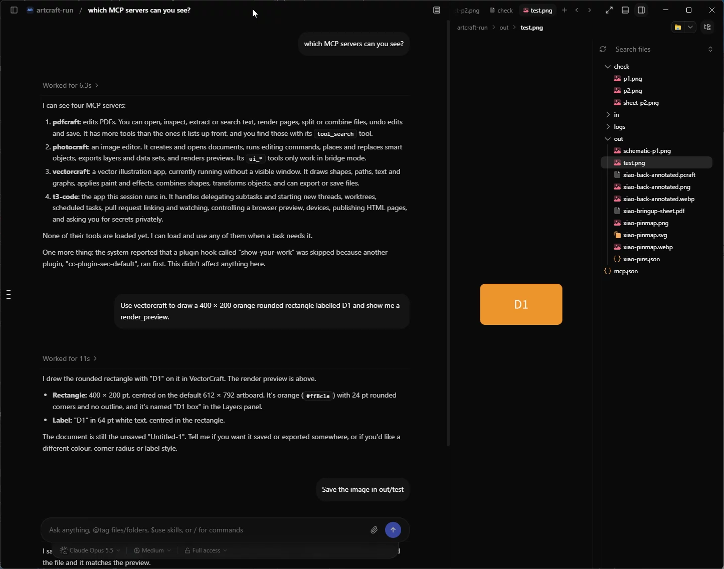
artcraft-run folder. Claude lists the MCP servers it can see, draws a test rectangle with VectorCraft, and exports it to out/test.png, shown on the right.Run it headless, so you can see every call
For this article I ran each stage with Claude Code's headless mode so that I had a complete transcript. The prompt goes in on standard input, --strict-mcp-config loads only the three servers from my file, and --allowedTools grants permission for the servers' tools without prompting. Anything not listed (a shell command, for example) is refused, because there is no one there to approve it:
PS C:\Users\Derek Molloy\artcraft-run> Get-Content logs\p1.txt | claude -p --strict-mcp-config --mcp-config mcp.json --allowedTools "mcp__pdfcraft" "Read" "Write" --output-format stream-json --verbose > logs\p1.jsonl
The stream-json output records every tool call, every result and, at the end, the number of turns, the elapsed time and the cost. A first check, before doing any work, is to ask Claude what it can see:
| MCP server  | Tools | Five example tools                                                   |
|-------------|-------|----------------------------------------------------------------------|
| pdfcraft    | 200   | doc_open, text_extract, page_render, form_fill, redact_apply         |
| photocraft  | 26    | doc_new, doc_open, command_run, render_preview, doc_export_layers    |
| vectorcraft | 33    | draw_shape, draw_path, set_paint, pathfinder, export                 |
Step 2: read the schematic with PdfCraft
The source document is Seeed's schematic for the XIAO nRF52840 Sense v1.1, a single-page PDF. I had planned to use the pin table in Nordic's nRF52840 Product Specification as well, but Nordic's documentation site returns an HTML page instead of the PDF to a scripted download, so the schematic became the only PDF source. For a board-level pin map it is the right one anyway: the product specification says what each port pin of the chip can do, and only the schematic says which of them Seeed connected to the header.
The prompt:
Use the pdfcraft tools to open in/xiao-nrf52840-sense-v1.1-schematic.pdf (Seeed's schematic for the XIAO nRF52840 Sense).
From it, work out which nRF52840 port pin (P0.xx or P1.xx) is wired to each XIAO header pin D0 to D10, plus the power pins, and the port pins for the onboard RGB LED and the charge LED.
Then read in/seeed_xiao_connector.dtsi (Zephyr's connector map) and cross-check the D0 to D10 mapping against it.
Write the result to out/xiao-pins.json as an array of {header, port_pin, schematic_net, dtsi_port_pin, agrees}. Also render the schematic page to out/schematic-p1.png at 200 dpi so I can check it by eye.
Finish with a short report: what you extracted, any disagreements, and anything you could not read from the PDF.
The first problem appeared on the second tool call. text_extract returned only the plot footer:
{"pages":[{"page":1,"text":"2022/6/24 14:52:49 f=0.51 D:\\Project\\XIAO改丝印\\XIAO改丝印 20220624\\202003398\\Seeed Studio XIAO nRF52840 v1.1.sch "}]}
doc_info showed the PDF was produced by EAGLE 6.4.0, which plotted every net label as vector strokes rather than text. There is no text layer to search. Claude then tried PdfCraft's OCR tool (ocr_words) on the region around the nRF52840 symbol, and the result was too fragmented to use, mostly single characters.
The next step was not one I had suggested. PdfCraft has a page_set_box tool that changes a page's crop box. Claude used it to crop the page to one small region at a time, rendered that region at 450 to 600 dpi with page_render, read the net names from the image, then called edit_undo to restore the page before moving to the next region. It did this six times, covering the nRF52840 module's pins, the header connector, the RGB LED and the charger. The source file was never saved, so it was not modified.
page_set_box {"doc": 1, "rect": [135, 660, 190, 728]}   → page now 55 × 68 pt
page_render  {"doc": 1, "page": 1, "dpi": 600}           → image
edit_undo    {"doc": 1}
page_set_box {"doc": 1, "rect": [265, 325, 330, 400]}   → page now 65 × 75 pt
...
The output file had one entry per pin:
{ "header": "D2", "port_pin": "P0.28", "schematic_net": "P0.28_AIN4_LOW_A2_D2", "dtsi_port_pin": "P0.28", "agrees": true },
{ "header": "D6", "port_pin": "P1.11", "schematic_net": "P1.11_TX_D6",          "dtsi_port_pin": "P1.11", "agrees": true },
All eleven header pins agreed with Zephyr's seeed_xiao_connector.dtsi. The RGB LED pins it read from the schematic (red P0.26, green P0.30, blue P0.06, common anode to 3V3, so active low) also match xiao_ble_common.dtsi, which I checked myself afterwards, because the prompt had not asked Claude to compare those.
The report was also clear about what it had not been able to settle. It found a net called P1.06_PWR_LED with nothing attached to it on the page, and left it out of the JSON rather than guessing. That is the behaviour I want, and the reason the prompt ends with "anything you could not read from the PDF". Without that line, a model is more likely to fill the gap.
Stage cost: 42 turns, 100 seconds, US$0.91.
Step 3: draw the pin map with VectorCraft
This is the stage I was most curious about. The prompt gave Claude four source files and a fairly detailed brief on layout and style:
Use the vectorcraft tools to draw a pin map for the Seeed XIAO nRF52840 as used by my Zephyr project, and export it as out/xiao-pinmap.svg and out/xiao-pinmap.png (1920 px wide).

Sources, all in in/:
- xiao-pins.json: header pin to nRF52840 port pin, extracted from the schematic and already checked.
- xiao_ble.overlay: what my firmware adds (an external LED on D2, active high; a button on D1, active low with pull-up).
- xiao_ble_common.dtsi and xiao_ble-pinctrl.dtsi: the board's own LEDs and the default UART, I2C and SPI pin assignments.

Layout: top view of the board, USB-C at the top. Left column top to bottom D0 to D6; right column top to bottom 5V, GND, 3V3, D10, D9, D8, D7. For each pin, a label pill outside the board with the header name, the port pin (P0.xx) and the default bus function where there is one (I2C SDA/SCL, UART TX/RX, SPI SCK/MISO/MOSI, analogue A0 to A5).
Highlight the pins my firmware claims (D1 button, D2 LED) in accent orange with a short note of the flags (e.g. ACTIVE_HIGH). Show the onboard RGB LED near the USB connector with its three port pins and "active low".
Add a title "XIAO nRF52840: pins used by xiao-devicetree" and a small legend.

Style ("Silicon Slate"): background #0F172A, board fill a slightly lighter slate, text #E2E8F0, accent orange #EA580C for firmware-claimed pins, circuit gold #EAB308 for power pins, electric blue #38BDF8 for bus functions. Font Inter for labels, JetBrains Mono for port pins. Canvas 1920 x 1080.

Check your work: render a preview, look at it, and fix overlaps or clipped text before exporting. Then report what you drew and any data you were unsure of. Do not invent pin functions that are not in the sources.
The layout instruction is there because I know the board from previous posts. I did not want Claude to work out the physical pin order from a photo, and it is not in any of the source files.
Claude started by calling command_list several times to find out which commands VectorCraft offers and what parameters they take. It then made a small test batch of three text objects to check that the fonts were installed. That test returned a warning: Inter has no "Bold" style on my machine. It switched to SemiBold for everything. After that it drew the whole diagram in four command_batch calls: one for the background, board outline, USB-C connector and module, one for the seven left-hand pins (57 commands), one for the seven right-hand pins (44 commands), and one for the RGB LED callout, legend and title. Each pin is a line, a pad ring, a rounded rectangle and three or four text objects:
{"id": "draw_shape", "params": {"shape": "ellipse", "x": 786, "y": 341, "width": 28, "height": 28,
  "fill": "#0F172A", "stroke": "#94A3B8", "strokeWidth": 5, "name": "pad-D0"}},
{"id": "draw_shape", "params": {"shape": "rectangle", "x": 430, "y": 333, "width": 310, "height": 44,
  "radius": 22, "fill": "#162032", "stroke": "#475569", "strokeWidth": 1.5, "name": "pill-D0"}},
{"id": "text.create", "params": {"x": 452, "y": 362, "text": "D0", "font": "Inter",
  "style": "SemiBold", "size": 20, "color": "#E2E8F0"}},
It then called render_preview, looked at the 1920 × 1080 image, found no overlaps, and exported the SVG and PNG. That is Figure 2 -- I have not edited it.
Some of the decisions in its report are ones I would have had to make myself:
- Analogue labels. The A0 to A5 labels are not in any devicetree file.
xiao_ble_common.dtsienables the ADC but defines no channels. Claude took them from the schematic net names and said so in the legend ("analogue An (schematic)"). It also pointed out that the board's A-numbers do not match the chip's analogue input numbers: D2 is A2 on the board but AIN4 on the nRF52840. That mismatch catches people out when they write ADC code for this board. - Which bus instances.
xiao_ble-pinctrl.dtsidefines pin states fori2c0,spi3, QSPI and PDM as well. Claude labelled only the instances thatseeed_xiao_connector.dtsinames as the XIAO's header buses (xiao_i2cisi2c1,xiao_spiisspi2,xiao_serialisuart0), and listed those at the bottom of the diagram. - What it left out. The charge LED on P0.17, the battery pad and the reset button were in the sources but not in the brief, and it said it had left them off rather than adding them.
One export choice needs a mention. The SVG has its text converted to outlines ("outlineText": true), so it renders correctly on a machine without Inter or JetBrains Mono, but the labels cannot be edited or searched, and the file is 600 KB. For a diagram I will regenerate from the sources, that is acceptable. If you want to edit the labels by hand later, ask for live text.
You can download the SVG and compare it with the PNG in Figure 2.
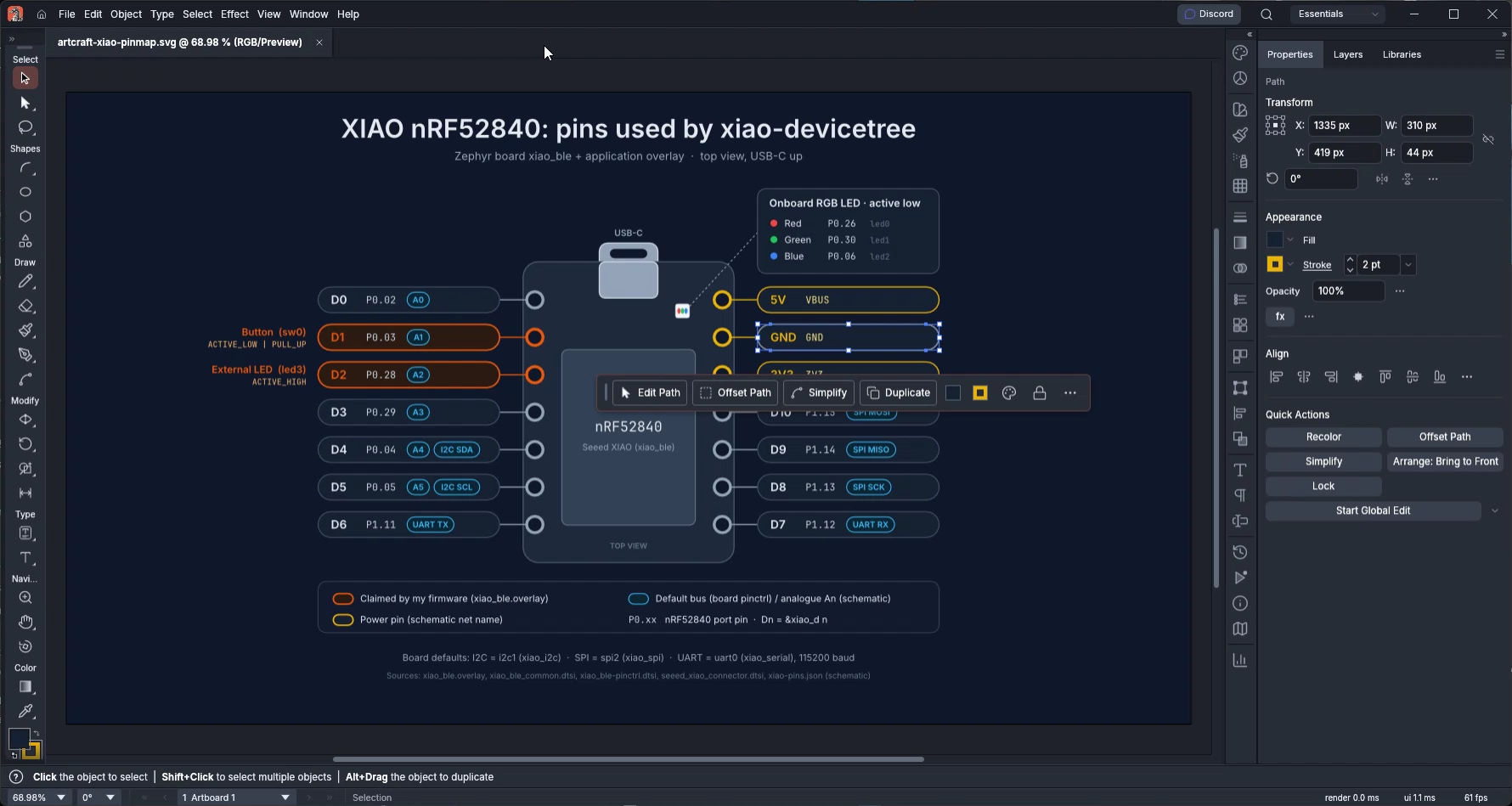
The SVG is also an ordinary VectorCraft document. Figure 4 shows it opened in the desktop app, with the GND pill selected. It is 310 × 44 px, the same size as the pill in the draw_shape call above, with a 2 pt gold stroke, and VectorCraft reads it back as a path. Shapes can be moved, restyled or added to by hand in the normal way, although the labels are outlines, as described above.
Stage cost: 31 turns, 4 minutes, US$1.47.
Step 4: annotate the board photo with PhotoCraft
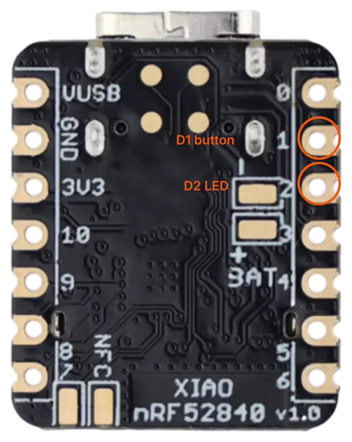
The pin map is a top view. When students solder header pins, they mostly look at the back of the board, where the pin numbers are printed. I wanted a photo of the back with the two pins my firmware uses marked in the same orange. The only photo I had was Seeed's product image, which shows both sides of the board side by side.
Use the photocraft tools for two jobs. Files are in in/, results go to out/.

1. in/xiao-board-photo.png is a product photo with two views of the XIAO nRF52840: the component side on the left and the back on the right (the back has the pin numbers printed on it). Crop out the back view only, with a small even margin. On a new layer, draw orange (#EA580C) rings around the pads printed "1" and "2", and add short labels in Inter, "D1 button" and "D2 LED", placed where they don't cover other pin numbers. Export it as out/xiao-back-annotated.webp at 1200 px wide, quality 85, and also save the layered document as out/xiao-back-annotated.pcd (or PhotoCraft's native format) so I can edit the labels later.

2. Convert in/xiao-pinmap.png to out/xiao-pinmap.webp at 1600 px wide, quality 85, for the blog.

Render a preview of the annotated photo and look at it before exporting: the rings must sit on the right pads. Report the file sizes and anything you had to guess.
To find the crop, Claude selected the white background to locate the board's edges, then cropped with a 12-pixel margin. It put the rings on their own layer and each label on a separate text layer, rendered previews four times while placing them, and saved the layered file in PhotoCraft's native .pcraft format (I had guessed the extension wrong in the prompt).
There were two details in its report that I would not have checked:
- Which pads. On the back of the XIAO, the digits "2" and "3" are printed next to the rectangular battery pads as well as next to the header pads. Claude ringed the edge pads and explained why. I checked against the overlay: D1 and D2 are header pins, so this is correct.
- Resolution. The back view in the product photo is only about 370 pixels wide. Making it 1200 pixels wide meant enlarging it about three times, so the photo is soft. Claude enlarged it before drawing, so the rings and text are sharp.
The second job, converting the pin map for the blog, was a single command: 1920 × 1080 PNG at 147 KB to 1600 × 900 WebP at 66 KB.
Stage cost: 38 turns, 90 seconds, US$1.06.
Step 5: assemble the bring-up sheet with PdfCraft
The last stage brings everything back into PdfCraft as a two-page A4 handout: the pin map on a landscape page, and the annotated photo with wiring and build instructions on a portrait page.
Use the pdfcraft tools to make a two-page A4 bring-up sheet for a lab handout, saved as out/xiao-bringup-sheet.pdf.

Page 1 (landscape): in/xiao-pinmap.png scaled to fill the page width with a 15 mm margin, and the heading "XIAO nRF52840: pin map for xiao-devicetree".
Page 2 (portrait): heading "Wiring and build"; in/xiao-back-annotated.webp at about 70 mm wide on the left; on the right, this text:
  External LED: D2 (P0.28) to 1 kOhm to LED anode, LED cathode to GND. Active high.
  Button: D1 (P0.03) to GND. Active low, internal pull-up.
  Build: west build -b xiao_ble xiao-devicetree -d build-xiao --pristine
  Flash: double-tap reset, copy build-xiao\zephyr\zephyr.uf2 to the XIAO-SENSE drive.
  Source of pin data: Seeed XIAO nRF52840 Sense v1.1 schematic, cross-checked against Zephyr's seeed_xiao_connector.dtsi.

Use Inter if available, otherwise Helvetica. Set the document title and author (Derek Molloy) metadata. Render each page and look at it before saving; fix anything clipped. Report the file size and anything PdfCraft could not do.
The first time I ran this, I allowed only the PdfCraft tools. PdfCraft's page_add_image does not accept WebP, so Claude tried to convert the photo: first with PhotoCraft (not permitted in that run), then with Python and Pillow (also not permitted), then by copying a PNG from another folder (outside PdfCraft's read root). Each was refused, and it saved the PDF with an empty space where the photo should be and a report asking me to approve one of the three options. I count that as the permission settings working as intended.
The fix was to allow both servers in the same run, and to give PdfCraft read access to the whole scratch folder so it could read what PhotoCraft wrote to out. On the second run, Claude used PhotoCraft to convert the WebP to a lossless PNG and placed that in the PDF. It also noticed in its own render that the west build command wrapped before --pristine, which a student copying it could miss, so it moved the command onto a line of its own at a slightly smaller size.
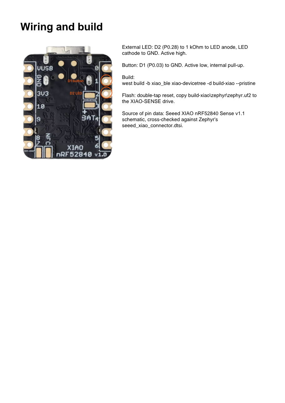
pdfcraft-cli render. Page 1 is the pin map from Figure 2 on an A4 landscape page.The full two-page sheet is available as a PDF (1.7 MB, A4).
What PdfCraft could not do:
- Fonts.
page_add_textoffers only the standard PDF fonts (Helvetica, Times and Courier), so the sheet is in Helvetica rather than Inter. - One font per text block. The build command cannot be set in Courier inside the same block as the other text. It would need a separate block positioned by hand.
- File size. The PDF is 1.7 MB, almost all of it the lossless PNG of the photo.
There is also a problem I should have caught in the brief. The pin map has a dark background, which looks right on screen and uses a lot of toner on a printed handout. For printed material I will ask VectorCraft for a light version of the same diagram, which is a one-line change to the prompt because the drawing is generated.
Stage cost: US$0.52 for the first run, US$0.45 for the second (29 turns, 64 seconds).
What the whole run cost
The costs are the figures Claude Code reported at API rates. On a Claude subscription, the same work counts against your usage limits instead. Most of the cost comes from images: every preview Claude renders and looks at is sent to the model, and the schematic stage sent several 600 dpi crops.
For comparison, the same set of outputs takes me a few hours by hand, mainly in the pin map. The more important difference is that the agent version can be repeated. The prompts are text files in logs\, so when the overlay changes I run stage 3 again.
Limits, and what I would check by hand
The apps are alpha. PdfCraft and PhotoCraft are labelled "Early alpha" and VectorCraft "In development". Tool names and parameters changed between the version the Craft Wiki documents (PdfCraft 0.19.0) and the one I installed (0.20.0). Prompts that name specific tools will break; prompts that describe the result you want, and let Claude discover the tools with command_list, are more robust to this.
Large tool lists cost context. PdfCraft's 200 tools are a lot of descriptions for the model to carry. Claude Code deferred them, so the model searched for the handful it needed (doc_open, text_extract, page_render and so on) at the start of the run rather than loading all 200. Other MCP clients may load the full list. PdfCraft has a --compact option that exposes a core set of tools plus a search tool, which I would use with any client that does not defer tools.
Data extraction needs a second source. The schematic stage worked because Claude had Zephyr's connector file to cross-check against. Where there was only one source (the LEDs and charger), the values were probably right, and I checked them, but a model reading a 600 dpi crop of a schematic can misread a 3 as an 8, as I can. For anything students will wire to, keep a second source in the prompt and ask for disagreements.
Rendering previews is what makes the drawing work. The VectorCraft stage produced a usable diagram on the first export because Claude rendered it and looked at it before exporting. Without the "render a preview, look at it, and fix overlaps" line, I would expect at least one overlapping label.
Permissions matter more in headless mode. In an interactive session, Claude Code asks before running a shell command. In headless mode with --allowedTools, anything not listed is refused. Several times, when an MCP tool could not do something, Claude tried to fall back to a shell command or a short Python script. Those were refused, and the automation roots refused writes outside out. I would rather the agent stop and report than work around a restriction, and with these settings that is what happened.
What this does not cover. I did not use the JSON control channel that lets an agent drive the visible desktop apps, FilmCraft or SoundCraft, or any of ArtCraft's generative AI tools. Everything here is deterministic editing, driven by an AI agent.
Where this fits
The bench harness article ended with my view that AI coding agents need access to real hardware to be trusted with firmware. This is the documentation side of the same view. An agent that can read the schematic, read the overlay and draw the diagram from both is less likely to produce documentation that disagrees with the code, because the documentation is generated from the same files the build uses. In a teaching lab, that matters: if the handout and the code disagree, students spend the session debugging the handout.
The next step for me is to make the pin map part of the project, with the prompt in the repository beside the overlay, so that changing a pin and regenerating the diagram is one action. I also want to try the same approach with a board that has a more complicated pin multiplexer, such as the STM32 Nucleo-F401RE, where the datasheet's alternate-function table is the hard part.
Further reading
- ArtCraft: getartcraft.com and the storytold organisation on GitHub
- PdfCraft AI-agent setup on the Craft Wiki
- VectorCraft AI-agent setup on the Craft Wiki
- PhotoCraft automation and AI agents on the Craft Wiki
- Model Context Protocol
- Connect Claude Code to tools via MCP (Claude Code documentation)
- Seeed XIAO nRF52840 Sense v1.1 schematic (PDF)
- My articles: The Zephyr devicetree: an interactive demo and Giving Claude Code a logic analyser