
The Zephyr Devicetree: An Interactive Demo
A gentle, but complete introduction to the Zephyr devicetree, taught through the one thing every beginner gets wrong - which way round an LED is wired. Built from nothing on a low-cost Seeed XIAO nRF52840, with three onboard LEDs, one external LED wired deliberately backwards, and a button.

Why Your LED Is On When You Told It Off: The Zephyr Devicetree, Explained
Here is a puzzle that has cost students many beginner-hours: You write a line of code that means "turn the LED off". You flash it. The LED comes on. So you change the code to say "on", because clearly the board is backwards, and now it goes off, and everything works. You move on with your work, mildly annoyed. Six months later somebody builds the same project on a different board and every LED is inverted.
That puzzle has a proper answer, and understanding why is a strong introduction to the single most important idea in modern embedded Linux and RTOS work: the devicetree. This article explains what a devicetree is, why it exists, and how to read and write one, using GPIO pins and LEDs as the example throughout because they are the simplest hardware there is and they still manage to be surprising!
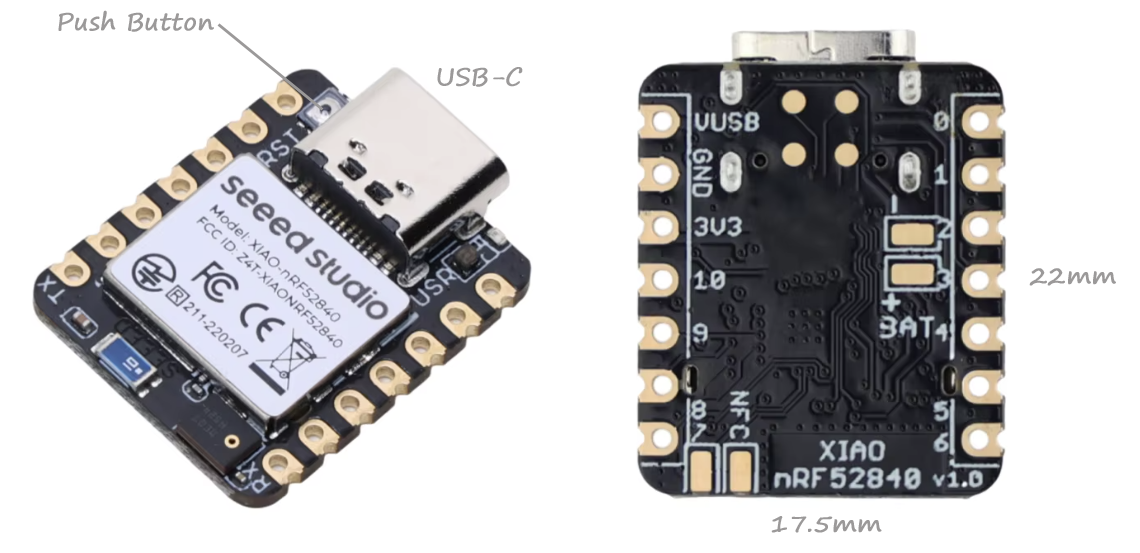
In order for this article and demo to be self contained, everything here is built from nothing on a Seeed XIAO nRF52840, a board smaller than a postage stamp that costs about €12. It has three LEDs already on it, so you can do most of this article with no wiring at all, and it plugs straight into USB (USB-C). By the end you will have three onboard LEDs, one external LED deliberately wired the opposite way round (to those onboard LEDs), and a button, all driven by code that does not know or care how any of them are connected.
xiao_ble board target. Zephyr moves quickly. Where something below does not match what you see, your board's own devicetree files are the valid source of information, and this article will show you exactly where to find them.Part 1: the idea
What problem is a devicetree solving?
Imagine you write a program that blinks an on-board LED. In the old way of doing things, somewhere in your code is a line saying which pin the LED is on:
#define LED_PIN 26 /* the LED is on pin 26 */
That works. It also means your program now contains a fact about one specific circuit board. Move to a board where the on-board LED is on pin 13 and you must edit your program. Move to a board where the LED is wired the other way round electrically and you must edit it again, in a different place, for a different reason. Support five boards and your once-simple program is riddled with #ifdef branches that have nothing to do with what the program is actually for.
The devicetree is the fix, and the idea is simple enough to state in one sentence:
Your code stops saying "pin 26" and starts saying "the LED called led0". Something else (such as a data file that ships with the board) says what led0 actually is. Change boards, change the data file, and the program is untouched. Only one such "something else" data file would be required for every program that runs on the board.
That "something else" is written in a language called devicetree source, in files ending .dts, .dtsi and .overlay. It was popularised for booting Linux on machines that could not describe themselves (an important topic in my Embedded Linux books), and Zephyr adopted it entirely. It is not a programming language: nothing in it executes. It is a description, and it is read entirely by the build system, before your program is even compiled.
led0" has already been reduced to a pin number and a pointer. There is no lookup, no dictionary, no cost. You get this flexibility for free.The one thing that actually causes the LED puzzle
Now back to the puzzle in the title, because the answer is a hardware fact that has to live somewhere, and the devicetree is where.
An LED needs current to flow through it in one direction. There are two sensible ways to wire one to a microcontroller pin:
- One end to ground. The pin goes high to light it. Current flows out of the pin. This is what most people picture, and we call the LED active high: a high voltage means "on".
- One end to the supply voltage. The pin goes low to light it, because now the current flows into the pin from the supply. This is called active low: a low voltage means "on".
Both are completely normal. Active low is extremely common on real boards, for reasons that are mostly about how much current a pin can safely sink versus source, and about what the pin does before your program starts.
So "turn the LED on" is not the same statement as "set the pin high". Whether those two mean the same thing depends on a wiring decision made by whoever designed the board, long before you got it.
Your XIAO's three LEDs are all active low. That is why the puzzle happens: you set the pin high, expecting light, and get darkness.
The devicetree's job is to record that fact once, in the right place, so that your program can go on saying "on" and "off" and always be right.
The Interactive Demo Version
The rest of Part 1 is much easier to see than to read. The interactive demonstration below builds the whole picture step by step: how a name in your code becomes a pin, where the flags come from, and what actually happens at the moment your program configures a pin.
Why your LED is on when you told it off
A GPIO in Zephyr is never just a pin number. It is a chain of lookups that the build system resolves before a line of your code runs, ending in a small struct your driver calls hold by reference. Almost every GPIO bug is a misunderstanding about one hop in this chain.
- The alias is the point of indirection. Your code says led0, the board says which node that is, and the same source builds for a different board. Break the alias and you get a build error, not a runtime surprise — which is the whole design intent.
- Three cells, not one. Controller, pin, flags. The third cell is the one people skim, and it is the one that decides what "on" means.
- Nothing here costs runtime. Every hop is resolved by the devicetree tooling into constants in devicetree_generated.h. The struct is filled at compile time.
Here is the thing that catches people. The flags controlling a pin come from two places — the devicetree cell and the argument you pass at runtime — and they are OR'd into a single word. Neither source can see what the other did.
- Polarity belongs in the devicetree, always. It is a fact about the board, not about your program. Putting it in C means the next board needs a code change, which is the thing devicetree exists to prevent.
- Pulls can legitimately come from either. A pull that the hardware requires belongs in the cell; one that is a property of how your code uses the pin can go in the call. Setting a pull up in one and down in the other is not an error the compiler can catch.
- The composite names are just OR'd sets. GPIO_OUTPUT_ACTIVE is output, plus an initial-value bit, plus a bit saying "that initial value is logical". Knowing that is enough to predict every one of them.
This is the bug everyone hits, so it is where the demo opens. The chain that explains it starts at .
This is the payoff for the whole abstraction, and the source of the bug in the title. gpio_pin_set_dt() takes a logical value — on or off, asserted or not. What voltage that produces is the devicetree's business, not yours.
- The double-inversion bug. An LED comes on when it should be off, so you flip the value in your C. Now the polarity is corrected twice and the code is wrong in a way that works — until someone reads the devicetree and "fixes" that too. Set the polarity in exactly one place.
- _raw is not a shortcut, it is a different contract. It says "I am talking about volts, and I accept that this code is now board-specific." Legitimate in a driver that owns the pin. A mistake in application code.
Between reset and your first line of C, the pin is not doing nothing — it is sitting in its reset state, usually disconnected. The instant gpio_pin_configure_dt() runs, it snaps to whatever your flags asked for, and the four GPIO_OUTPUT_* options do not agree about what that should be.
- Physical and logical initialisers are not interchangeable. GPIO_OUTPUT_LOW means zero volts whatever the board says. GPIO_OUTPUT_INACTIVE means off, and lets the devicetree decide the voltage. On an active-low board those two are opposites.
- Use the logical pair by default. If you write GPIO_OUTPUT_INACTIVE everywhere, your start-up state stays correct when the hardware polarity changes under you. That is the entire benefit, and it costs nothing.
- The gap before configure() matters when the pin drives something real. A high-Z line into a MOSFET gate or a relay driver is not a safe default. Where it matters, the fix is a pull resistor on the board, not a faster boot.
The same logical/physical split runs through inputs, where it is much easier to miss — because on a typical active-low button with a pull-up, GPIO_INT_EDGE_FALLING and GPIO_INT_EDGE_TO_ACTIVE do exactly the same thing. Until the polarity changes, and then only one of them is still correct.
- Prefer the logical interrupt flags. EDGE_TO_ACTIVE means "when the button is pressed" on every board. EDGE_RISING means "when the voltage goes up", which is a statement about one board's wiring.
- A floating input has no defined idle level and will happily generate interrupts from nothing at all. If the board has no external pull, the cell or your configure() call must supply one.
- Debouncing is not the driver's job. One press produces a burst of perfectly real edges. Handle it with a timer, a work item with a resubmit delay, or hardware — but expect it.
The decision, reduced. Almost every GPIO choice comes down to one question: is this fact about the board, or about my program?
- Default to the logical family. _dt functions, ACTIVE/INACTIVE initialisers, EDGE_TO_ACTIVE interrupts. Reach for the physical names only when you mean volts, and write a comment saying why.
- Put board facts in the overlay, not the app. A wrong pull-up in a devicetree overlay is a two-line fix on one board. The same fix in C is a conditional that grows a new branch per board forever.
- When it misbehaves, print the struct. spec.pin and spec.dt_flags at boot will tell you in one line whether you are debugging your code or your devicetree. Usually it is the devicetree.
Deliberate omission: this demo shows no numeric flag values anywhere. The bit positions inside gpio_flags_t are an implementation detail that has moved between releases, and code that depends on them is broken by definition. Everything shown here is the documented semantics, which have been stable since the logical/physical split was introduced.
The interactive demo opens on the tab that explains the LED puzzle, and tab 0 walks the chain from the start. The pin numbers and the polarity match your XIAO, so the devicetree snippets it shows should be the ones you are about to find on your own board. Drag the pin slider and watch every panel follow.
Part 2: Practical set up
Why this board?
The Seeed XIAO nRF52840 is a good place to learn this because it removes almost every obstacle:
The flashing method matters too. Many boards need a separate hardware debugger before you can put code on them. The XIAO does not: double-tap the reset button and it appears on your computer as a USB memory stick. You copy a file onto it. That is the whole procedure. I noted this in my other articles – the button is really tiny but it is there, just beside the USB-C connector.
.dts file", that instruction works for every board Zephyr supports. The demo above is set up for the XIAO's pins and polarity, but the pin slider will take it anywhere you like, and everything except the numbers is board-independent by construction.Installing Zephyr from nothing
This assumes Windows. The official Getting Started Guide covers Linux and macOS, where the shape is identical and only the first step differs. I mainly use Linux but I have chosen Windows for this article as it is by far the OS that is most common in my student cohorts.
Be warned that this is the least enjoyable part of Zephyr. It downloads several gigabytes and takes a while. It is also a one-time cost: once the workspace exists, you never do this again.
Step 1: the prerequisites. Chocolatey is the smoothest route on Windows, because it is what the Zephyr documentation assumes. From an elevated PowerShell -- right-click, "Run as Administrator":
choco install cmake --installargs 'ADD_CMAKE_TO_PATH=System'
choco install ninja gperf python git dtc-msys2 wget 7zip
Two of those are easy to miss and annoying to diagnose. gperf is used during the build and nothing tells you it is absent until something fails obscurely. And that ADD_CMAKE_TO_PATH=System argument makes CMake visible to scripts, not just to the terminal you are typing in.
PATH variable when a terminal starts, so newly installed tools are invisible to windows that were already open. Every "command not recognised" error at this stage is this.Step 2: the workspace. Zephyr lives in a workspace: one folder holding the Zephyr source, the extra libraries it depends on, and your own projects, all side by side.
mkdir C:\zephyr
cd C:\zephyr
python -m venv zephyrproject\.venv
zephyrproject\.venv\Scripts\Activate.ps1
pip install west
Your prompt gains a (.venv) prefix. That is a Python virtual environment, which keeps Zephyr's Python tools from interfering with anything else on your machine.
west is Zephyr's own command-line tool. It fetches the source, builds it, and flashes it as follows:
west init zephyrproject
cd zephyrproject
west update
west zephyr-export
west packages pip --install
Go and make coffee! west update is the multi-gigabyte download.
Step 3: the compiler. Zephyr needs a cross-compiler, which is a compiler that runs on your PC but produces code for the Arm chip on the board. That plus a few other tools is the Zephyr SDK:
west sdk install
Step 4: know where things are. This layout catches everybody at least once:
C:\zephyr\                     <- just a container
├── zephyr-sdk\                <- the compilers. Nothing you edit.
└── zephyrproject\             <- THE WORKSPACE. Your projects go here.
    ├── .venv\
    ├── modules\               <- libraries Zephyr depends on
    └── zephyr\                <- THE ZEPHYR SOURCE
        ├── boards\            <- every supported board lives here
        ├── dts\               <- devicetree bindings
        └── samples\           <- example programs
The trap is that there are two folders one inside the other, and both are called "Zephyr". zephyrproject is the workspace; zephyrproject\zephyr is the source. Samples are in the inner one. Your projects go in the outer one.
C:\zephyr\zephyrproject.venv\Scripts\Activate.ps1 and cd C:\zephyr\zephyrproject. If you get west: command not found it means you skipped the first. A build that cannot find its source means you skipped the second.Proving it works
Before writing anything, build somebody else's program:
(.venv) PS C:\zephyr\zephyrproject> west build -b xiao_ble zephyr\samples\basic\blinky -d build-blinky --pristine
-- west build: generating a build system
If that finishes with a table of memory usage rather than an error, everything is installed correctly.
--pristine does, and when you need it. It deletes the build folder and starts fresh. You need it when you point an existing build folder at a different board or a different program, or if you move the workspace. You do not need it for ordinary edits to your own code. To stop thinking about it altogether, run west config build.pristine auto once and west will decide for you.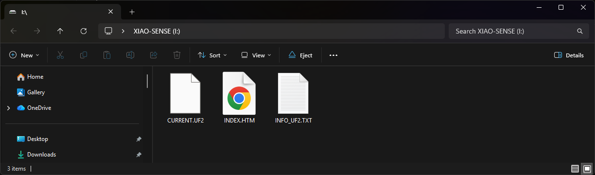
Now flash it. Plug the XIAO in, then double-tap the reset button — the tiny button next to the USB socket. The board will appear as a USB drive. Copy the file across:
(.venv) PS C:\zephyr\zephyrproject> copy .\build-blinky\zephyr\zephyr.uf2 I:\
(.venv) PS C:\zephyr\zephyrproject>          <-board disconnects from Windows
Replace I: with whatever drive letter appeared. The drive disappears as soon as the copy completes, which is normal and means it worked: the board reset itself and started running your code. A red LED now blinks once a second.
Video 1. The off-the-shelf test program with the RGB LED flashing red.
Take a moment to think about this program, because there is already something to notice. You built blinky (a program written by somebody who has likely never heard of the XIAO) and it found the correct LED on the correct pin. It did that using the devicetree. In the next section we look at how.
Part 3: reading your board's devicetree
Finding the file
Every board in Zephyr describes itself in a folder under zephyr\boards. The XIAO nrf52840 BLE is here:
C:\zephyr\zephyrproject\zephyr\boards\seeed\xiao_ble\
Open xiao_ble_common.dtsi in a text editor. Ignore most of it and find this segment of the file:
leds {
	compatible = "gpio-leds";

	led0: led_0 {
		gpios = <&gpio0 26 GPIO_ACTIVE_LOW>;
		label = "Red LED";
	};

	led1: led_1 {
		gpios = <&gpio0 30 GPIO_ACTIVE_LOW>;
		label = "Green LED";
	};

	led2: led_2 {
		gpios = <&gpio0 6 GPIO_ACTIVE_LOW>;
		label = "Blue LED";
	};
};
There is your board, described in data. Three LEDs. Their pins. And, in that third position, the answer to the puzzle this article opened with: GPIO_ACTIVE_LOW, written down once, by the person who designed the board.
A bit further down is a second piece:
aliases {
	led0 = &led0;
	led1 = &led1;
	led2 = &led2;
	pwm-led0 = &pwm_led0;
	mcuboot-led0 = &led0;
	watchdog0 = &wdt0;
};
The four ideas in that snippet
Devicetree has a small vocabulary, and those twenty lines contain most of it.
Nodes. Everything is a node, and nodes nest inside each other to form a tree. leds is a node; the three LEDs are nodes inside it. A node describes one thing: a chip, a bus, a peripheral, an LED.
Properties. Each node holds properties, written name = value;. label is a property. So is gpios.
Labels. The led0: before led_0 is a label, a nickname you can use to refer to this node from elsewhere in the tree using &led0. Think of it as a bookmark. Confusingly, the label and the node name are often similar; they are different things.
The compatible property. This is the important one, and it is usually explained badly. compatible = "gpio-leds" is a claim about what kind of thing this node is. It is how the build system decides which driver, if any, should take an interest, and which rules the node has to follow.
compatible. When the build sees compatible = "gpio-leds", it goes looking for a matching binding — a file in zephyr\dts\bindings\ that describes what properties a node of this kind may and must have. The binding is what makes gpios mean something. It is also what tells Zephyr that a driver exists for this and that it should be compiled in.This is why a devicetree is not just a configuration file. It is a set of claims, checked against published schemas, at build time. Misspell a property and the build stops. Miss a required one and the build stops. You find out at your desk rather than on the bench, which is the entire point.
The three cells
Now the line that matters most:
gpios = <&gpio0 26 GPIO_ACTIVE_LOW>;
The angle brackets hold a list of values, and in devicetree jargon each value is a cell. There are three here, and each answers a different question:
How many cells there are, and what they mean, is not fixed by Zephyr. It is decided by the controller: gpio0 declares #gpio-cells = <2>, meaning "anyone referring to me must supply two values after the reference". The reference itself is the third. Different kinds of controller ask for different numbers.
The alias, and why your code says led0
The aliases block is the last link, and it is slightly confusing:
aliases {
	led0 = &led0;
};
That appears to say nothing whatsoever. It looks like it defines led0 as led0, which would be either a tautology or a typo. It is neither – it teaches two pieces of devicetree syntax at once.
Read it right to left. The thing on the right already exists. The name on the left is new. So this line creates an alias called led0 and points it at something that is already in the tree. The & means "the node labelled". Devicetree borrows the symbol from C, where & gives you the address of something rather than its value, and it means much the same here. &led0 is not the text "led0"; it is a reference to an actual node somewhere else in the file. The proper term for such a reference is a phandle (short for pointer handle) and you will meet the word in error messages, so it is worth knowing.
Which is where the apparent tautology comes from. The two led0s are different kinds of name that happen to be spelled the same way. In fact three names are in play here, and separating them makes the whole thing obvious. Look again at the node:
led0: led_0 {
	gpios = <&gpio0 26 GPIO_ACTIVE_LOW>;
	label = "Red LED";
};
Nothing forces the alias and the bookmark to match. To prove it to yourself, this would be entirely legal:
aliases {
	dereks_torch = &led0;
};
and your program would then ask for DT_ALIAS(dereks_torch). Everything else stays exactly as it is. The board's authors chose the name led0 because that is the name Zephyr's sample programs look for, and they gave the node a matching bookmark so the file reads tidily. The price of that tidiness is a line that looks like it does nothing.
&led0 rather than just led0? Because the & is what makes the build check it. A phandle is resolved by the devicetree tooling into a real link to a real node, so misspell it and the build stops with an error naming the label it could not find. Without the &, the right-hand side would be an ordinary string, the file would compile happily, and you would discover the mistake at some later and less convenient moment.You will see the same
&label notation in exactly three places, and it means the same thing in all of them:- Pointing at a node from a property, as in
gpios = <&gpio0 26 ...>: "the controller labelled gpio0".- Giving a node a second name, as in
led0 = &led0; inside aliases.- Reopening a node to change it, as in
&i2c1 { status = "disabled"; }; at the top level. We use this one in Part 6 to take a pin back from a peripheral.Once you read
& as "the node labelled", every one of those stops needing a separate explanation.Samples like blinky are written against the alias led0. That is a convention meaning "the first LED, whatever and wherever it is". The board says which node the name refers to. That indirection is the reason a sample written years ago by a stranger lit the correct LED on your board.
Notice mcuboot-led0 = &led0 in that same block. It says the red LED is also the one the bootloader uses as its indicator. Two different pieces of software, one LED, and the devicetree is where they agree about it. It is also why you may see the red LED flicker for an instant when the board resets, before your program has done anything at all.
Putting the chain together
So the full journey, which the demo's first tab animates, is:
your code says          DT_ALIAS(led0)
the aliases block says  led0 means the node labelled led0
that node says          gpios = <&gpio0 26 GPIO_ACTIVE_LOW>
the build produces      { port: gpio0, pin: 26, flags: active-low }
And in C, one macro collapses all of it:
static const struct gpio_dt_spec red = GPIO_DT_SPEC_GET(DT_ALIAS(led0), gpios);
gpio_dt_spec is a small struct with three fields: the controller, the pin, and the flags. Every Zephyr GPIO function whose name ends in _dt takes one of these, which is how those functions are able to know about the polarity and do the correct thing for you.
Part 4: on, off, and volts
Two families of function
Here is the payoff for all of that additional description. Zephyr gives you two ways to set a pin, and the difference is important:
gpio_pin_set_dt(&red, 1);     /* "turn it ON"    - logical  */
gpio_pin_set_raw(&red, 1);    /* "drive it HIGH" - physical */
The first is logical. You are saying on. Zephyr reads the flags from the devicetree, sees GPIO_ACTIVE_LOW, and drives the pin low, because that is what "on" means for this LED on this board.
The second is physical. You are saying high volts, and Zephyr does exactly that, ignoring the devicetree entirely.
On your XIAO, gpio_pin_set_dt(&red, 1) and gpio_pin_set_raw(&red, 1) do opposite things.
_dt functions and think in terms of on and off. Let the devicetree deal with volts. The _raw functions are not a shortcut, they are a different contract: they say "this code is about voltages and is therefore specific to one board". That is a legitimate thing to want inside a driver. It is almost never what you want in an application.The double-inversion bug
Now we can name the mistake from the opening properly. You call gpio_pin_set_dt(&red, 1) expecting light. Suppose you have the polarity flag wrong, or missing. The LED stays dark. So you change your code to gpio_pin_set_dt(&red, 0) and it lights up. Working code, problem solved, move on.
Except the polarity is now corrected twice: once wrongly in the devicetree and once wrongly in your C, and the two errors cancel. Your program is inverted, and it only looks correct because of a second bug. When someone later reads the devicetree, spots the mistake and fixes it properly, every LED in your program inverts and nobody will know why!
Fix polarity in exactly one place, and let that place be the devicetree. If an LED is behaving backwards, the flag is the first thing to check, not the last.
Tab 2 of the demo lets you flip every one of these switches and watch a simulated LED respond, including a truth table of all the combinations.
Part 5: the first program
Enough theory! Create a project folder inside the workspace, alongside zephyr:
C:\zephyr\zephyrproject\xiao-devicetree\
│   CMakeLists.txt
│   prj.conf
└───src
        main.c
CMakeLists.txt — three lines that turn a folder into a Zephyr application:
cmake_minimum_required(VERSION 3.20.0)
find_package(Zephyr REQUIRED HINTS $ENV{ZEPHYR_BASE})
project(xiao_devicetree)

target_sources(app PRIVATE src/main.c)
prj.conf — configuration. For now, one line, saying "I intend to use GPIO pins":
CONFIG_GPIO=y
src/main.c:
/* Three onboard LEDs, one at a time.
 *
 * Notice what is NOT in this file: no pin numbers, and nothing about how
 * the LEDs are wired. Both of those are facts about the board, and the
 * board's devicetree already knows them.
 */
#include <zephyr/kernel.h>
#include <zephyr/drivers/gpio.h>

/* Ask for the three LEDs by their standard alias names. The macro reads
 * the devicetree at BUILD time and fills in a small struct: which GPIO
 * controller, which pin, and how the board wired it.
 */
static const struct gpio_dt_spec red   = GPIO_DT_SPEC_GET(DT_ALIAS(led0), gpios);
static const struct gpio_dt_spec green = GPIO_DT_SPEC_GET(DT_ALIAS(led1), gpios);
static const struct gpio_dt_spec blue  = GPIO_DT_SPEC_GET(DT_ALIAS(led2), gpios);

static const struct gpio_dt_spec *leds[] = { &red, &green, &blue };

int main(void)
{
	/* GPIO_OUTPUT_INACTIVE means "make this an output, and start it OFF".
	 * Note OFF, not LOW. On this board, off happens to be a high voltage,
	 * and that is precisely the detail we are refusing to care about.
	 */
	for (int i = 0; i < 3; i++) {
		if (!gpio_is_ready_dt(leds[i])) {
			return 0;
		}
		gpio_pin_configure_dt(leds[i], GPIO_OUTPUT_INACTIVE);
	}
	int n = 0;

	while (1) {
		gpio_pin_set_dt(leds[n], 1);          /* on  */
		k_msleep(400);
		gpio_pin_set_dt(leds[n], 0);          /* off */

		n = (n + 1) % 3;
	}
	return 0;
}
Build and flash it:
(.venv) PS C:\zephyr\zephyrproject> west build -b xiao_ble xiao-devicetree -d build-xiao --pristine
-- west build: making build dir C:\zephyr\zephyrproject\build-xiao pristine
-- west build: generating a build system
Loading Zephyr default modules (Zephyr base).
...
[192/192] Linking C executable zephyr\zephyr.elf
Memory region         Used Size  Region Size  %age Used
           FLASH:       45136 B       788 KB      5.59%
             RAM:       13560 B       256 KB      5.17%
        IDT_LIST:           0 B        32 KB      0.00%
Generating files from C:/zephyr/zephyrproject/build-xiao/zephyr/zephyr.elf for board: xiao_ble/nrf52840
Converted to uf2, output size: 90624, start address: 0x27000
Wrote 90624 bytes to zephyr.uf2
...
(.venv) PS C:\zephyr\zephyrproject> copy build-xiao\zephyr\zephyr.uf2 I:\
(.venv) PS C:\zephyr\zephyrproject>
Red, green, blue, repeating. Roughly twenty lines, and not one of them mentions a pin.
Video 2. The repeating red, green, blue pattern on the on-board RGB LED.
gpio_is_ready_dt() is not boilerplate you can drop. Devicetree describes hardware that should exist; this function asks the driver whether it actually initialised. On a simple GPIO port it will essentially always succeed, so it is tempting to skip. Get into the habit anyway, because the moment a device sits behind a bus that might not have come up, this check is the difference between a clear failure and a mystery.Try breaking it
Two experiments worth two minutes each, because both teach something the working version cannot.
Swap one function for its physical twin. Change the first LED's line to gpio_pin_set_raw(&red, 1). The red LED now stays off when it should be on and on when it should be off, while green and blue behave. You have just reproduced the article's opening puzzle deliberately.
Break the alias. Change DT_ALIAS(led0) to DT_ALIAS(led9). The build fails, with an error, at your desk. It does not compile to something that silently does nothing. That failure is a feature, and it is the reason to prefer aliases over guessing.
Part 6: your own devicetree, and an LED wired backwards
The board's devicetree describes what the board's designer put there. Anything you add is your business to describe, and you do that in an overlay: a small file that is merged on top of the board's devicetree at build time. This is where the article's central claim gets tested. We will add one external LED, wired the opposite way to the three onboard ones, and drive it with exactly the same C code.
First, which pins are even free?
Before wiring anything, a question a beginner would not think to ask, and whose answer is sitting in the devicetree.
The XIAO exposes eleven pins, labelled D0 to D10 on the silkscreen. They are not all available. The board's devicetree switches several peripherals on by default, and those peripherals have already claimed pins. Reading xiao_ble-pinctrl.dtsi alongside the connector file tells you exactly which:
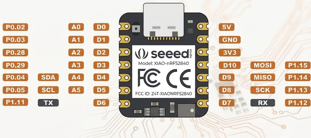
Only four pins are actually free. That is not a limitation someone chose to inflict on you; it is the board being useful out of the box, with its buses ready to go. But it is the kind of thing that costs an hour if you discover it by wiring to D8 and wondering why nothing happens.
And because it is all in the devicetree, you can take a pin back. Adding this to your overlay switches the I²C peripheral off and returns D4 and D5:
&i2c1 {
	status = "disabled";
};
status is a standard property meaning "is this node in use". Setting it to disabled tells the build not to include the driver and not to claim the pins. We do not need it for this project, but it is worth knowing that the answer to "can I have that pin back" is two lines rather than a redesign.
&i2c1 { ... }; is how you edit somebody else's node. The board's devicetree already defined i2c1. That syntax reopens the existing node by its label and adds or changes properties. It is the mechanism behind every overlay: you are not replacing the board's description, you are amending it.The circuit
We will use D2 for the LED and D1 for a button. Both are free. For the LED, wire it the ordinary Arduino way, which is the opposite of how the onboard ones are done:
(A) and connects to the resistor; the short leg, on the flat side of the
LED body, is the cathode (K) and goes to GND. Fit it the other way round and
nothing lights — a diode blocks current in reverse.
The long leg of an LED is the anode and goes toward the positive side, which here is the pin. So the pin has to go high to light it. This LED is active high.
For the button, simpler still: one leg to D1, the other to GND. Nothing else, as there is an internal pull-up resistor. Pressing it connects D1 to ground, so a press makes the pin go low. This button is active low.
What an nRF52840 pin can actually deliver, and the constraint that is not in the datasheet. The numbers here are worth having, because they are much tighter than the Arduino world's and because the most restrictive one is documented in an unexpected place. From the GPIO electrical specifications in the nRF52840 Product Specification, per pin, with the supply at 2.7 V or above:
Read those as capability under a condition, not as a ceiling on what will flow. The figures are quoted at the point where the output is still within 0.4 V of its rail, so what they really say is "this much current while still looking like a valid logic level". Push past it and current still flows; the pin just stops being a trustworthy 1 or 0.
Two things in that table are worth noticing. The default is a 2 to 4 mA part, which is why 1 kΩ and roughly 1.3 mA is a comfortable choice and 220 Ω is not. And sinking is slightly stronger than sourcing, 15 mA against 14 mA, which is one of several reasons board designers so often wire LEDs active low: the pin pulling down is the pin doing what it is marginally better at.
Now the part that is not in the datasheet at all, and it is the constraint that will actually limit what you build. On popular forums, Nordic's engineers state that 15 mA is the maximum for one pin and the total for every pin in the package added together, and that the total is a single shared budget covering sinking and sourcing at once. In their own words: "you should not let combined sink and source current of all GPIOs exceed 15 mA at any time."
So you do not get 15 mA for pulling low and another 15 mA for driving high. One pin sinking 5 mA while another sources 5 mA has already spent 10 mA, leaving 5 mA for everything else on the chip.
That is worth a moment's thought, because it sounds arbitrary. Sinking current flows out through the ground pins and sourcing current comes in through the supply pins, so why should they share a budget? Because the limit is not really about the pads. It is about the silicon between them: the internal power rails feeding the GPIO block, the on-chip routing, and the risk of ground bounce or latch-up when too much current moves through that structure at once, whichever direction it happens to be going. The pins are the visible ends of a shared internal resource.
Compare all of this with an ATmega of the Arduino Uno era, rated for tens of milliamps on a single pin and hundreds across the package, and you can see why the habits do not transfer. On an Uno you can hang eight LEDs off eight pins at 15 mA each without thinking. Here that is eight times the whole chip's budget.
Three consequences, and they all matter for the project you are building:
- Absolute maximums are not design targets. They are the point at which the manufacturer stops promising the part survives. Design well below them.
- Count every lit LED on the board, in both directions. The three onboard LEDs sink, the external one sources, and all four land in the same 15 mA. Their series resistors were chosen by Seeed rather than by you and are not recorded anywhere in the devicetree, so this is a number to measure rather than assume. Part 7 works it through.
- Anything beyond a couple of indicators should not be powered from a pin. Use a transistor, a MOSFET or a dedicated LED driver, and let the pin carry information rather than power. On this chip that threshold arrives much sooner than you would expect.
There is a broader lesson in where that package figure lives, and it is one worth carrying into every datasheet you read. The binding constraint on a design is not always in a table. Sometimes it is in an application note, an errata sheet, or a support engineer's reply on a forum, and the only way to find it is to go looking and to ask. I searched for the same answer on the BeagleBone AM3359 and despite a 4,700 page datasheet, it was only ever described online. A number that is documented only in correspondence still constrains your hardware exactly as much as one printed in the specification.
zephyr/dt-bindings/gpio/nordic-nrf-gpio.h: include <zephyr/dt-bindings/gpio/nordic-nrf-gpio.h>and gpios = <&xiao_d 2 (GPIO_ACTIVE_HIGH | NRF_GPIO_DRIVE_H0H1)>; where S means standard and H means high, and the two letters set the low side and the high side independently, so S0H1 is standard when pulling down and high when driving up. H0H1 asks for high drive in both directions. Reaching for those is what moves a pin from the 2 to 4 mA row of the table above to the 9 to 10 mA one.This is worth seeing for a reason beyond LEDs. Earlier the article said the third cell holds "flags describing how the board wired it", and the examples were all generic Zephyr flags like
GPIO_ACTIVE_LOW. The drive-strength flags are vendor-specific: they exist only for Nordic parts, they are defined in a Nordic header, and a devicetree written with them will not build for an ST or Espressif chip. That is the trade the third cell makes. Generic flags travel everywhere; vendor flags let you reach the silicon's real capabilities at the cost of portability. Knowing which kind you are using is important.None of this raises the package total. High drive changes how hard an individual pin pulls and how well it holds a valid logic level under load; it does nothing for what the chip as a whole can pass. And you do not need it here: at 1.3 mA the LED sits well inside standard drive, which is the default, which means the tidiest thing about the 1 kΩ choice is that it lets you ignore this entire subject.
The overlay
Create boards\xiao_ble.overlay inside your project:
(.venv) PS C:\zephyr\zephyrproject> tree /f .\xiao-devicetree\
Folder PATH listing
Volume serial number is 0000025B D2E8:0917
C:\ZEPHYR\ZEPHYRPROJECT\XIAO-DEVICETREE
│   CMakeLists.txt
│   prj.conf
├───boards
│       xiao_ble.overlay         <- new
└───src
        main.c
The filename matters: west automatically picks up an overlay in a boards folder named after the board target. Build for a different board later, add a differently-named file, and change nothing else.
/*
 * Everything we added to the board ourselves.
 *
 *   D2  an LED to GND through 1k.  Pin goes HIGH to light it  -> ACTIVE_HIGH
 *   D1  a button to GND.           Pin goes LOW when pressed  -> ACTIVE_LOW
 *
 * Note the contrast with the board's own LEDs, which are ACTIVE_LOW. That
 * difference is recorded here and nowhere else, which is the entire point.
 */
/ {
	/* A second group of LEDs, in the same style the board itself uses. */
	external_leds {
		compatible = "gpio-leds";

		led_ext: led_ext {
			gpios = <&xiao_d 2 GPIO_ACTIVE_HIGH>;
			label = "External LED on D2";
		};
	};

	buttons {
		compatible = "gpio-keys";

		button0: button_0 {
			/* Two flags, OR'd together. ACTIVE_LOW says a press
			 * reads as low; PULL_UP asks the chip to hold the pin
			 * high when nothing is pressing it. Without the pull,
			 * the pin would float and read nonsense.
			 */
			gpios = <&xiao_d 1 (GPIO_ACTIVE_LOW | GPIO_PULL_UP)>;
			label = "Button on D1";
		};
	};

	/* Give our two additions standard names, so main.c can ask for them
	 * the same way it asks for the onboard LEDs.
	 */
	aliases {
		led3 = &led_ext;
		sw0  = &button0;
	};
};
The two new ideas in that file
&xiao_d 2 instead of &gpio0 28. Both would work. The first is better, and the reason is a devicetree feature worth knowing. The XIAO's board files define a node representing the physical connector:
xiao_d: connector {
	compatible = "seeed,xiao-gpio";
	#gpio-cells = <2>;
	gpio-map = <0 0 &gpio0 2 0>,        /* D0 */
		   <1 0 &gpio0 3 0>,        /* D1 */
		   <2 0 &gpio0 28 0>,       /* D2 */
		   /* ... */
		   <6 0 &gpio1 11 0>,       /* D6 */
		   /* ... */
};
That gpio-map is a translation table, and a node like this is called a nexus node. It lets you write &xiao_d 2 (i.e., "pin D2 of the connector") and have the devicetree work out that this means pin 28 of gpio0. Look at D6 in that list and you can see why it is useful: D6 is not even on the same controller as D0 through D5, it is on gpio1. The silkscreen hides that, and so does the nexus node.
Use the connector name and your overlay matches what is printed on the board and what you are actually looking at while wiring. Use the raw pin and you are one transcription error away from significant confusion.
Next:compatible = "gpio-keys". We are describing a button, so we use the standard binding for buttons. It costs nothing, it validates our node against a published schema, and it means a future version of this project could hand the button to Zephyr's input subsystem without redescribing the hardware.
compatible implies. There is a gpio-keys driver in Zephyr that turns button presses into input events. We are not enabling it as we are going to read the pin ourselves. The node is still worth declaring properly, because compatible is a description of what the thing is, which stays true regardless of who chooses to act on it. This is a useful thing to understand: the devicetree describes the hardware, and enabling drivers is a separate decision made in prj.conf.Part 7: the payoff
Now the program that proves the argument. Update src/main.c:
/* Four LEDs and a button.
 *
 * Three LEDs are on the board and wired ACTIVE LOW.
 * One LED is on a breadboard and wired ACTIVE HIGH.
 *
 * Look for a single line below that treats them differently.
 * There isn't one.
 */
#include <zephyr/kernel.h>
#include <zephyr/drivers/gpio.h>

static const struct gpio_dt_spec red   = GPIO_DT_SPEC_GET(DT_ALIAS(led0), gpios);
static const struct gpio_dt_spec green = GPIO_DT_SPEC_GET(DT_ALIAS(led1), gpios);
static const struct gpio_dt_spec blue  = GPIO_DT_SPEC_GET(DT_ALIAS(led2), gpios);
static const struct gpio_dt_spec ext   = GPIO_DT_SPEC_GET(DT_ALIAS(led3), gpios);
static const struct gpio_dt_spec btn   = GPIO_DT_SPEC_GET(DT_ALIAS(sw0),  gpios);

static const struct gpio_dt_spec *leds[] = { &red, &green, &blue, &ext };
#define N_LEDS ((int)(sizeof(leds) / sizeof(leds[0])))

/* Set by the interrupt handler, read by main. volatile tells the compiler
 * this can change behind its back, so it must not optimise the check away.
 */
static volatile bool pressed;

static struct gpio_callback btn_cb;

static void on_button(const struct device *dev, struct gpio_callback *cb,
		      uint32_t pins)
{
	static int64_t last;
	int64_t now = k_uptime_get();

	/* A mechanical switch does not close once, it bounces. Ignore
	 * anything within 200 ms of the last accepted press to debounce.
	 */
	if (now - last > 200) {
		last = now;
		pressed = true;
	}
}

int main(void)
{
	for (int i = 0; i < N_LEDS; i++) {
		if (!gpio_is_ready_dt(leds[i])) {
			return 0;
		}
		gpio_pin_configure_dt(leds[i], GPIO_OUTPUT_INACTIVE);
	}

	if (!gpio_is_ready_dt(&btn)) {
		return 0;
	}
	gpio_pin_configure_dt(&btn, GPIO_INPUT);

	/* Register the callback BEFORE switching the interrupt on. The other
	 * order leaves a window in which an edge fires with nobody listening.
	 */
	gpio_init_callback(&btn_cb, on_button, BIT(btn.pin));
	gpio_add_callback(btn.port, &btn_cb);

	/* EDGE_TO_ACTIVE means "when the button becomes pressed". Not "when
	 * the voltage falls" -- that would be a statement about this wiring.
	 */
	gpio_pin_interrupt_configure_dt(&btn, GPIO_INT_EDGE_TO_ACTIVE);

	int n = 0;
	bool paused = false;

	while (1) {
		if (pressed) {
			pressed = false;
			paused = !paused;
		}

		if (!paused) {
			gpio_pin_set_dt(leds[n], 1);
			k_msleep(400);
			gpio_pin_set_dt(leds[n], 0);
			n = (n + 1) % N_LEDS;
		} else {
			/* Paused: hold every LED on, including one wired the
			 * opposite way to the other three. One call, one
			 * meaning, four different voltages.
			 */
			for (int i = 0; i < N_LEDS; i++) {
				gpio_pin_set_dt(leds[i], 1);
			}
			k_msleep(50);
		}
	}
	return 0;
}
Build, flash, and watch. The cycle now runs across four LEDs, three of them on the board and one on your breadboard. Press the button and all four light together and stay lit.
(.venv) PS C:\zephyr\zephyrproject> west build -b xiao_ble xiao-devicetree -d build-xiao
-- west build: making build dir C:\zephyr\zephyrproject\build-xiao
-- west build: generating a build system
...
-- Zephyr version: 4.4.99 (C:/zephyr/zephyrproject/zephyr), build: v4.4.0-7043-g777ab585520e
[192/192] Linking C executable zephyr\zephyr.elf
Memory region         Used Size  Region Size  %age Used
           FLASH:       45404 B       788 KB      5.63%
             RAM:       13560 B       256 KB      5.17%
        IDT_LIST:           0 B        32 KB      0.00%
Generating files from C:/zephyr/zephyrproject/build-xiao/zephyr/zephyr.elf for board: xiao_ble/nrf52840
Converted to uf2, output size: 91136, start address: 0x27000
Wrote 91136 bytes to zephyr.uf2
--pristine this time? Look at the "making build dir" line: this is a fresh configure, so there is nothing stale to discard. You would need it if you dropped a new overlay into a build directory that had already been configured without one, because west decides which overlay files apply at configure time and then caches the answer.Video 3. The final version -- the momentary push button stops the cycle and lights all of the LEDs. Pressing again allows the cycle to continue.
That is the whole article in one video (Video 3). Four LEDs on. Three of the pins are sitting at 0 V and one is at 3.3 V. Your code said 1 to all of them.
It is also the moment this project draws the most current it ever will, so let us count it. Recall the 15 mA shared package budget from Part 6. With all four LEDs lit, three pins are sinking and one is sourcing, and every one of them counts against the same total. Your external LED is the easy part: 1 kΩ at 3.3 V, minus roughly 2 V across the LED, gives about 1.3 mA. The onboard three are the unknown, because Seeed chose their resistors and the devicetree does not record them. Two plausible cases:
The first case is comfortable. The second is not: 13 mA against a 15 mA ceiling leaves almost nothing, and running a demo at ninety per cent of a chip's absolute maximum is not something to do casually.
Either way, notice what the exercise demonstrates. You cannot answer "is this circuit safe?" from the code, or from the devicetree, or from the datasheet alone. You needed the wiring, the resistor values, the direction of each current, and a limit that is documented on a forum. That is what hardware work actually feels like, and it is worth meeting on four LEDs rather than on something expensive.
What to try next
- Swap the polarity in the overlay. Change the external LED to
GPIO_ACTIVE_LOWand rebuild without touchingmain.c. It now behaves backwards. That one-line experiment demonstrates that the behaviour really is coming from the devicetree. - Move the LED to D3. Change
<&xiao_d 2 ...>to<&xiao_d 3 ...>, move the wire, rebuild. Again,main.cis untouched. - Wire the LED the other way (i.e., to 3.3 V instead of GND, so it becomes active low like the onboard ones) and set the flag to match. Same code, third wiring, still correct.
Part 8: two details that matter later
The moment a pin is configured
Between the board powering on and your first line of C, a pin is not doing what you think. It sits in its reset state, which for most chips means disconnected: not high, not low, just floating.
The instant gpio_pin_configure_dt() runs, it snaps to whatever you asked for. And there are four ways to ask, which fall into two families:
On an active-high board, INACTIVE and LOW do the same thing, which is exactly how the wrong habit forms without anyone noticing. On your XIAO's active-low LEDs they are opposites: GPIO_OUTPUT_LOW turns the LED on at start-up.
Use GPIO_OUTPUT_INACTIVE unless you specifically mean volts. Tab 3 of the demo draws this as a timeline for all four options at once.
There is a real-world issue here worth knowing about. That floating period before configuration is harmless for an LED. It is not harmless if the pin drives a motor controller, a relay, or a MOSFET gate, where "undefined" can mean "on". When that matters, the fix is a pull-down resistor on the circuit board, not faster software.
Inputs, pulls and bounce
Three things about the button are worth spelling out. A floating input is not zero. An input pin with nothing driving it does not read low, it reads whatever stray charge happens to be on the track, and it will change its mind constantly and generate interrupts from nothing. Our button connects D1 to ground when pressed, and to nothing at all when released. GPIO_PULL_UP in the overlay is what makes "released" mean something: it switches on a resistor inside the chip that gently holds the pin high. Delete that flag and the program misbehaves in a way that looks like a hardware fault. That deserves discussion, because "floating" is one of those words that gets used long before anybody explains it, and the explanation is useful.
What is actually going on
Physically, an unconnected input pin is a small piece of copper (the pad, the track, the bond wire) attached to the gate of a transistor that draws almost no current at all. Call it a few picofarads of capacitance and a leakage current measured in nanoamps. There is no resistor anywhere, so there is nothing to decide what voltage that copper sits at.
So what does it read? The answer is that there is no defined value, and that is the entire problem. What actually happens is that the pin holds whatever charge it last acquired and then drifts, slowly, in whichever direction the leakage happens to favour. Because a few nanoamps into a few picofarads moves the voltage at a rate of volts per second, it can hold a stale value for a surprisingly long time, then wander.
Where it tends to wander to is the nasty part. A CMOS input decides between 0 and 1 by comparing the pin against a threshold roughly midway between the rails, so on a 3.3 V part the deciding line sits somewhere around 1.5 V. A floating pin very often settles near that threshold, which is the single worst place it could be, for two separate reasons:
- Your reads become meaningless. The pin is sitting right on the fence, so the buffer's answer is decided by microvolts of noise. Note that the reading is never "floating": a digital input has exactly two possible answers, and it will confidently give you one of them, then the other, thousands of times a second.
- It costs you current. An input buffer parked at mid-rail has both of its transistors partly switched on, so a small current flows straight from the supply to ground through the input stage, doing nothing. On a coin-cell design whose sleep budget is a couple of microamps, a handful of floating inputs can dominate the entire power consumption. This is not a theoretical concern; it is one of the classic reasons a battery device that should last a year lasts a fortnight.
Charge arrives from everywhere. A signal switching on a neighbouring track couples through the capacitance between them. Mains wiring in the walls couples through the air, and so does your own body, which is why waving a hand near a floating input reliably produces a burst of 50 Hz interrupts and is the fastest way to demonstrate the effect on a bench. Longer tracks and dangling wires make better aerials, which is why a floating pin on a breadboard misbehaves far more entertainingly than one buried in a PCB.
Seen this way, a pull resistor is not really "setting the pin high". It is providing a path low enough in impedance that arriving charge drains away faster than it can accumulate. The nRF52840's internal pull is somewhere around 13 kΩ, which against a picofarad or two of coupling settles the pin in nanoseconds. The signal you care about, a finger on a button, is many orders of magnitude slower than that, so the resistor rejects the noise and passes the press.
Floating is not the same as high impedance
These two get used interchangeably, including in places you would expect better, and they describe different things. The distinction matters the moment you are debugging.
High impedance is a statement about a driver. It means an output has deliberately stopped driving, so it is imposing nothing on the wire. That is a useful, intentional, entirely well-defined state: it is how several devices share one bus without fighting, and how a pin gets out of the way so something else can talk.
Floating is a statement about a wire. It means nothing at all is driving that node, so its voltage is undefined.
The two are related but not equivalent. A high-impedance pin on a net that something else drives is perfectly happy, and the net's voltage is perfectly well defined. A net only floats when nobody is driving it. If it helps: high impedance is a pin declining to speak, and floating is a wire with nobody speaking to it.
There is a third state worth knowing, because it is the one people actually mean when they reach for "high-Z" as a safe default:
The interesting row is the second last one. Zephyr's GPIO_DISCONNECTED turns the input buffer off as well as the driver, so nothing is sampling the pin at all. The voltage is still undefined, but now nobody is asking, so there is no mid-rail current and no phantom interrupts. That is why it is the right choice for a pin you are finished with, and why it is different from leaving a pin as a floating input.
The chip designers agree with all of this, incidentally. The nRF52840 does not come out of reset with its pins as inputs; it comes out with the input buffers disconnected. The default state of a Nordic GPIO is the one row in that table with no downside, and enabling an input is an explicit decision you make. Once you know why, that stops looking like an odd default and starts looking like good practice.
Logical interrupts, again. We asked for GPIO_INT_EDGE_TO_ACTIVE, meaning "when the button becomes pressed". The alternative, GPIO_INT_EDGE_FALLING, means "when the voltage goes down" and would work identically here, because our button is active low. Change the wiring to active high and EDGE_FALLING silently starts firing on release while EDGE_TO_ACTIVE stays correct. Same principle as the LEDs: describe the intent, let the devicetree handle the volts.
Bounce is real. A mechanical switch does not close cleanly. Its contacts bounce for a few milliseconds, producing a burst of perfectly real edges, and your interrupt handler will run for every one. That is what the 200 ms guard in the callback is for. Demo tab 4 shows the burst and counts the callbacks.
Troubleshooting
- The build fails with an error about a node or alias. Almost always a typo in the overlay, or a name that does not exist. The error text names the property. Check the build actually used your overlay: look for its path in the build output, and confirm the filename exactly matches the board target,
xiao_ble.overlay. - The external LED never lights. Check the long leg faces the resistor and the pin, not ground. Then check you used D2 and not D4 or D8, which belong to other peripherals. Then try the polarity flag.
- The external LED is on when it should be off. The polarity flag is wrong. Fix it in the overlay, not in
main.c– that is the double-inversion trap. - The onboard LEDs are inverted. You have probably used a
_rawfunction or aGPIO_OUTPUT_LOW/HIGHinitialiser somewhere. - The button does nothing at all. Measure D1 against GND with the button disconnected. It must read about 3.3 V, because the pull-up is holding it there. If it does, the fault is in the switch or its wiring. If it reads 0 V with nothing attached, the pull-up is not reaching the pin: check
GPIO_PULL_UPis in the overlay, and that the overlay is actually being applied. - The button does nothing, and D1 sits at 0 V even when released. You have almost certainly taken both wires from the same internally-connected pair of a four-pin tactile switch, which is a permanent short to ground. Use diagonally opposite legs. Note the second symptom this produces: because the pin is already active when
gpio_pin_interrupt_configure_dt()runs,GPIO_INT_EDGE_TO_ACTIVEnever sees a transition, so no amount of pressing produces an edge. - The button works but feels sluggish. Expect up to 400 ms of lag. The interrupt itself fires immediately, but
main()only looks at thepressedflag between LED steps, and it spends most of each step asleep ink_msleep(400). A quick tap during a long sleep still registers, it just takes until the current LED finishes. If that bothers you, the fix is not a shorter sleep: replace the flag with a semaphore the loop can wait on, which is the standard Zephyr answer and a good next exercise. - One press does several things. Bounce. Increase the guard interval.
- The board will not appear as a USB drive. Double-tap reset faster; the window is short and the button is tiny. A charge-only USB cable will also do this, and is a classic waste of an hour.
west: command not found. The virtual environment is not active in this terminal.
The rules, condensed
Everything in this article above reduces to one question you can ask about any piece of information: is this a fact about the board, or a fact about my program?
And three best practices that follow from it:
- Default to the logical family:
_dtfunctions,ACTIVE/INACTIVEinitialisers,EDGE_TO_ACTIVEinterrupts. Reach for_raw,HIGH/LOWandEDGE_RISINGonly when you genuinely mean voltages, and leave a comment saying why. - Board facts go in the overlay. A wrong flag in a devicetree is a one-line fix on one board. The same fix in C becomes a conditional that grows a new branch for every board, forever.
- When something misbehaves, suspect the devicetree first. It usually is.
Where this leaves you
You have installed a real RTOS toolchain, read a manufacturer's hardware description, written your own, and driven four LEDs wired two different ways with code that knows about neither. That is the devicetree's entire promise, demonstrated at the smallest possible scale.
The same ideas scale up without changing shape. A temperature sensor on an I²C bus is a node with a compatible, an address and a reference to the bus, and your code asks for it by alias exactly as it asked for led0. A whole board port is thousands of lines of the same vocabulary you have just learned: nodes, properties, labels, phandles, status.
Two natural next steps. If you want to go deeper into devicetree, the interesting question is where bindings come from and how you write one for a part Zephyr has never heard of. If you want to go wider, the same board has a Bluetooth radio, an 802.15.4 radio and a microphone, all described in that same file you opened in Part 3.
Whichever you pick, you will not have to guess which pin anything is on again.

