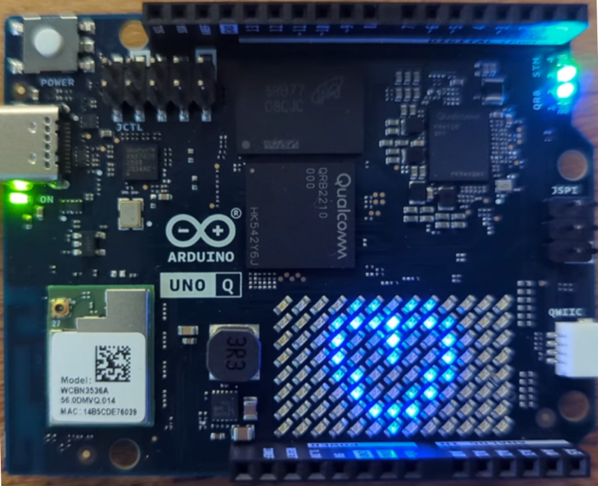
A Real Dual-Brain Application on the Arduino UNO Q: an AI Brick, a Camera, and a Presence Lamp
Part two of the UNO Q series puts the board's dual-brain design to real work - a vision AI Brick on the Linux side detects a person through a camera, and the microcontroller side turns that into a smoothly breathing lamp that never stutters, no matter how hard the AI is working.

A Real Dual-Brain Application on the Arduino UNO Q
This guide is a real application with an AI Brick, a camera, and hardware output. Part 1 covered the architecture, first boot, and the Bridge RPC mechanism; this part assumes that groundwork.
Part 1 ended with a deliberately tiny App: Python measured the CPU load, the microcontroller blinked accordingly, and the point was the "seam" between the two processors. This part keeps the same architectural lesson and builds on both sides of the seam. The Linux side gets a harder job: running a vision AI model against a live camera feed. The microcontroller side gets a real-time job: rendering a smooth LED animation that must not stutter. And the seam between them remains a single function call.
The application is a presence lamp. A camera watches a real-world space; when the AI Brick sees a person, an LED on the microcontroller side breathes gently up and down; when the person leaves, it fades out. A live web view (with detection boxes drawn over the video) is the "hello world" of edge AI, chosen because every part of it is legible, and because it sets up the closing argument: a stress test that shows why the animation lives on the MCU, something no single-processor board can demonstrate as cleanly.
Video 1. A demonstration of the overall system where the LED pulses when a human (an online photo of me in this example) is visible in the mobile phone video stream. The CPU on the Arduino Uno Q is doing the video processing work and the the MCU is performing the deterministically smooth LED pulsing when a human is detected. Apologies for the "Inception" overtones.
What a Brick actually is
Part 1 introduced Bricks briefly as "pre-packaged capabilities for the Linux side". Before building on one, an engineer will want to understand what this means.
A Brick is a packaged service plus the Python client for talking to it. When your App declares a Brick, App Lab provisions the service on the Debian side (the heavyweight ones, such as vision models, run as containers), starts and stops it with your App's lifecycle, and exposes a small Python class in your main.py through which you consume it. Bricks register with the same MessagePack-RPC router that carries the MPU-to-MCU Bridge from Part 1, which is elegantly consistent: your Python, your sketch, and the AI model are all just clients on one star network, calling functions on each other by name.
The declaration lives in the App's app.yaml manifest. This is what it looks like for the two Bricks this project uses (App Lab writes this for you when you add Bricks through the UI; it is still worth reading what it wrote – it even added the smiley icon!):
name: presence_lamp
description: ""
ports:
- 8080
bricks:
- arduino:video_object_detection:
    devices:
    - remote_camera_0
- arduino:web_ui
icon: 😀
Before the line-by-line notes, two things about the form of this file. A network port in an embedded board's manifest can look out of place, but it is the heart of this design: the UNO Q is a network peer, and the phone reaches it over the LAN through port 8080, so the "wiring" between sensor and board is a socket, not a cable. The identifiers follow a convention too: arduino: prefixes an official, Arduino-supplied Brick (a third-party Brick would sit under its own namespace), while devices are named by kind and numbered from zero, so remote_camera_0 is simply the first remote camera -- plug in a second phone and it would be remote_camera_1.
app.yaml file is read-only inside App Lab. The editor shows it but will not let you change it, and there is no "add a raw device" button for remote_camera_0. To make an edit to the file above you have to go around App Lab: SSH into the board and edit the file in place, for example:ssh arduino@<your-board>.local nano ~/ArduinoApps/presence_lamp/app.yaml # make any editsthen restart the App (
arduino-app-cli app start ~/ArduinoApps/presence_lamp, or press Run in App Lab) so the new manifest is picked up. This is why starting from the "Detect Objects on Smartphone Camera" example is the smoother path: it already ships this manifest, so you never touch it by hand.A few things about that file require attention:
devices: [remote_camera_0]is the line that makes this a smartphone-camera app, and it is the single most common thing to get wrong. It tells the vision Brick to bind to a remote camera streamed over the network, rather than a local USB/UVC device. Omit it (as the plain "Detect Objects on Camera" example does) and the Brick provisions against a local camera, finds none, and aborts startup withmissing required device: no camera found-- which also means the web UI never comes up and the phone has nothing to pair with. So "no camera found" and "the QR never appears" are the same bug. (Using a USB webcam instead? This is where a local device id would go.)ports: [8080]exposes the port the phone streams video to. The QR code the board shows carries this port (you will spot...&port=8080in the pairing URL); if 8080 is closed, or your Wi-Fi isolates clients from one another, the phone pairs but no frames arrive.arduino:video_object_detectionis the vision workhorse: it owns the (remote) camera feed, runs an object-detection model against the frames, and streams results (labels, confidences, bounding boxes) to your Python. The default model is a general-purpose object detector that knows the everyday classes ("person" among them), an.eimfile from Edge Impulse; current App Lab versions manage models from an AI models tab, so swapping in a custom-trained one later is a menu action rather than a config-file safari. That path (train on your own data in Edge Impulse, deploy as.eim, select in App Lab) is the natural Part 2½ of this series for anyone whose lamp should respond to their cat instead.arduino:web_uiserves an App-provided web page from the board (anassets/folder in your App, talking to your Python over WebSockets) athttp://<board>.local:7000. One caveat that trips people up: the Brick serves whatever is inassets/, and a from-scratch App gets only an empty scaffold (<!-- Add your HTML here -->), so the page renders blank. The pairing-QR-then-live-video UI is not automatic; it is the smartphone example'sassets/(itsindex.html,app.js,qrcode.min.js, and images), which consumes thewelcomemessage your Python sends and draws the QR, then embeds the processed video feed. So "lean on the default UI" really means "keep the example'sassets/folder" -- the point is that you still write no web code, not that the Brick invents a camera page. Theassets/mechanism is complex and deserves its own article.
Nothing about the Bridge story from Part 1 changes.
Hardware: which camera?
The UNO Q has no camera of its own, and its one USB-C port is also its power inlet, which therefore provides the following options:
| Option | What you need | Notes |
|---|---|---|
| USB webcam | A UVC webcam + a powered USB-C hub/dock | The hub must feed the board 5 V/3 A while hosting the camera; unpowered hubs are the classic source of boot loops. Plain UVC cameras (the Logitech Brio-class ones are widely reported working) need no drivers. |
| Your phone | The Arduino IoT Remote app + a (free) Arduino Cloud login | App Lab shows a QR code; the phone app scans it and streams its camera to the board. You must be signed into Arduino Cloud in the app for the pairing handshake (the QR only carries a one-time code, not credentials), but the video itself flows over your local Wi-Fi, not the cloud. The phone is "just the sensor"; all inference stays on the UNO Q. Requires the App to be built for a remote camera (the app.yaml above). |
| An external LED for the lamp | LED + ~220 Ω resistor on a PWM (~) header pin, e.g. ~D9 |
Optional; the on-board user LED works for a first run (on/off only, no breathing). |
The phone route is worth highlighting for teaching settings: assuming students have a phone, it removes the only hardware purchase between a bare UNO Q and a working vision project, and because the "sensor" is wireless, the camera can be across the room from the board. For a permanently installed presence lamp, the webcam is the right long-term answer.
Here is a video capture of my phone acting as the video stream source for the UNO Q. You can also stream accelerometer and other sensors:
cloud.arduino.cc/installmobileapp link), so while the app is in use you are sharing account and connection data with Arduino. The camera video still streams locally over your Wi-Fi, not to the cloud, but the dependency and the sign-in are real. For a classroom or a privacy-sensitive setting, or for a permanent install, the USB webcam avoids the phone, the app, and the account entirely.The App
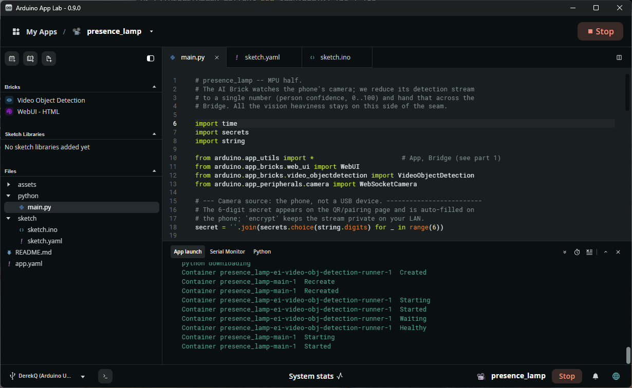
The quickest correct start is to open the bundled "Detect Objects on Smartphone Camera" example and save it as presence_lamp (use the Copy and Edit App option at the very top right): it already carries the remote_camera_0 binding, port 8080, and the assets/ folder that draws the pairing QR, so you inherit a working camera path and only add the lamp.
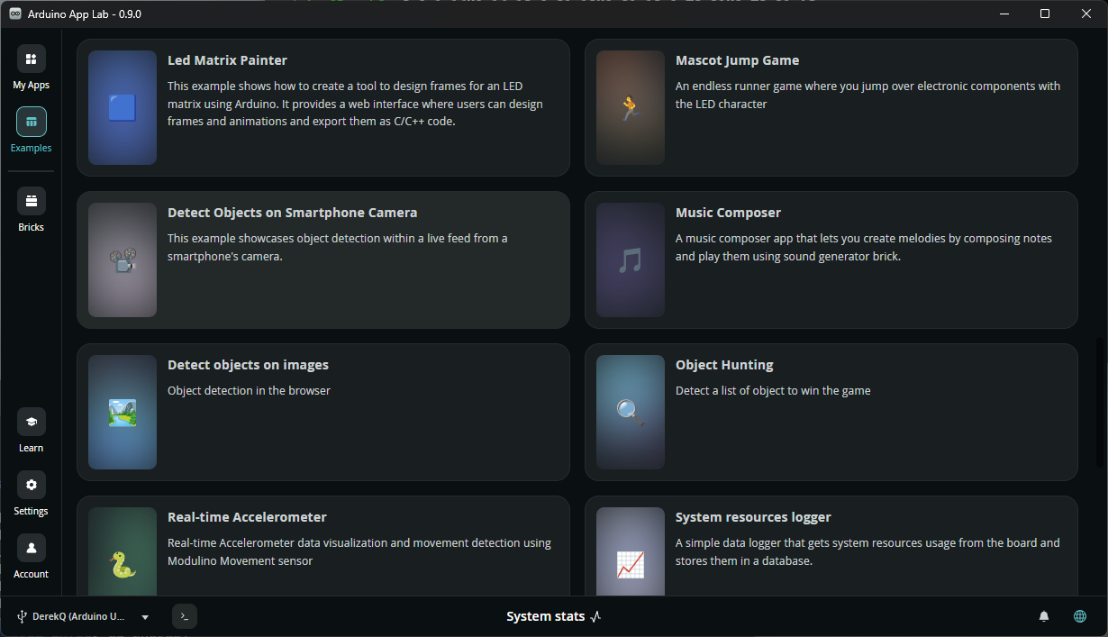
Note that the "Detect Objects on Smartphone Camera" example is Linux-only: it ships a python/main.py and an assets/ folder but no sketch/ component, because Arduino's version never touches the microcontroller. Our presence lamp does, so the one thing the example cannot give you is exactly the half that makes this a dual-brain project.
In summary, after copying the example you will:
- Create the
sketch/folder yourself. There is no "add a sketch" button; App Lab only lets you add files and folders. So make a folder calledsketch/in the App and put two files in it -- App Lab (andarduino-app-cli) reject the folder withsketch folder is incomplete: both sketch.ino and sketch.yaml are requiredif either is missing:sketch.ino– the Zephyr half below. - Press Run (or
arduino-app-cli app start ...). Withsketch.yamlpresent, App Lab compiles the.inofor thearduino:zephyrplatform and uploads it to the MCU as part of starting the App. - Adapt
python/main.py-- keep the example's camera/QR wiring, but replace its detection-to-UI plumbing with the presence policy below, whose one job isBridge.call("presence", ...). That call is where the new sketch and the existing Python meet.
sketch.yaml – a five-line manifest that selects the MCU target. There is no board Fully Qualified Board Name (FQBN) to hunt for; every UNO Q example uses it verbatim:
profiles:
  default:
    platforms:
      - platform: arduino:zephyr
default_profile: default
devices: [remote_camera_0] line and the port yourself, exactly as above (forgetting it is the "no camera found" trap), and copy the example's assets/ folder over: a from-scratch Web UI Brick gives you a blank page, not the QR/video UI.Either way, confirm app.yaml matches the listing above, then fill in the two halves. The folder shape is Part 1's, plus the Brick declarations and the Web UI assets/.
I have presented below a pruned tree of my project to show you how the rich UI of the web interface dominates the overall project file structure. This is why using the sample project simplifies the overall project setup, even if it leaves the web UI requiring future work to make it application specific.
arduino@DerekQ:~/ArduinoApps$ tree -F presence_lamp/
presence_lamp//
├── app.yaml*
├── assets/
│   ├── app.js*
│   ├── docs_assets/
│   │   ├── iot-remote.png*
│   │   └── mobile-object-detection.png*
│   ├── fonts/
│   │   ├── fonts.css*
│   │   ├── Open Sans/
│   │   │   ├── OFL.txt*
│   │   │   └── OpenSans-VariableFont_wdth,wght.ttf*
...
│   ├── img/
│   │   ├── barcode.svg*
│   │   ├── camera.svg*
...
│   │   ├── plant.webp*
│   │   └── stars.svg*
│   ├── index.html*
│   ├── libs/
│   │   ├── arduino.js*
│   │   ├── qrcode.min.js*
│   │   └── socket.io.min.js*
│   └── style.css*
├── python/
│   └── main.py
├── README.md*
└── sketch/
    ├── sketch.ino
    └── sketch.yaml

10 directories, 38 files
Design before code
One decision defines the whole application: what crosses the seam? The camera frames must not (megabytes per second, and the MCU could do nothing with them); the raw detection stream should not (it is bursty, and it would put the smoothing logic on the wrong side); what crosses is one integer, occasionally: a confidence percentage, zero meaning "nobody here". Linux turns complex vision into a clean scalar; the MCU turns that scalar into LED light. Deciding what crosses a processor boundary, and keeping it small, is most of heterogeneous design, and this project is a worked example.
The Linux half (python/main.py)
# presence_lamp -- MPU half.
# The AI Brick watches the phone's camera; we reduce its detection stream
# to a single number (person confidence, 0..100) and hand that across the
# Bridge. All the vision heaviness stays on this side of the seam.

import time
import secrets
import string

from arduino.app_utils import *                       # App, Bridge (see Part 1)
from arduino.app_bricks.web_ui import WebUI
from arduino.app_bricks.video_objectdetection import VideoObjectDetection
from arduino.app_peripherals.camera import WebSocketCamera

# --- Camera source: the phone, not a USB device. -------------------------
# The 6-digit secret appears on the QR/pairing page and is auto-filled on
# the phone; encrypt keeps the stream private on your LAN.
secret = ''.join(secrets.choice(string.digits) for _ in range(6))

ui = WebUI()
camera = WebSocketCamera(secret=secret, encrypt=True, resolution=(480, 640))
camera.on_status_changed(lambda evt, data: ui.send_message(evt, data))

# The Web UI page needs these details to draw the pairing QR code.
ui.on_connect(lambda sid: ui.send_message("welcome", {
    "client_name": camera.name, "secret": secret, "status": camera.status,
    "protocol": camera.protocol, "ip": camera.ip, "port": camera.port,
}))

# --- The tunables that are ours: presence policy. -----------------
# confidence filters weak guesses at the source; debounce_sec spaces
# the inferences (the A53s can do a few per second).
detector = VideoObjectDetection(camera, confidence=0.60, debounce_sec=0.20)

last_seen = 0.0          # when we last saw a person
last_confidence = 0
HOLD_SECONDS = 2.0       # keep the lamp alive briefly after they leave

def on_detections(detections):
    """Called by the Brick: {label: [{'confidence': .., ..}, ..], ..}."""
    global last_seen, last_confidence
    people = detections.get("person", [])
    if people:
        last_seen = time.time()
        last_confidence = int(max(p["confidence"] for p in people) * 100)
        Bridge.call("presence", last_confidence)

def loop():
    # The fall-off path: detections only fire when someone IS there,
    # so absence is our own timeout to notice and report.
    global last_confidence
    if last_confidence and (time.time() - last_seen) > HOLD_SECONDS:
        last_confidence = 0
        Bridge.call("presence", 0)
    time.sleep(0.25)

detector.on_detect_all(on_detections)
App.run(user_loop=loop)
Strip the camera-pairing boilerplate (i.e., the secret, the WebUI wiring, the welcome message, all of it lifted straight from Arduino's example) and what remains is quite short, and note how little of that is actually "AI": the model, the camera, the frame pipeline, and the inference loop are all inside the Brick. Your code is the "policy": what counts as a person (confidence threshold), how absence is decided (the hold timer), and what the rest of the system gets told (one integer). That is the correct layer for application code to live at, and it is also, not coincidentally, the layer that is easy to unit test.
arduino.app_bricks.video_objectdetection, arduino.app_peripherals.camera), the VideoObjectDetection(camera, confidence=, debounce_sec=) signature, and the on_detect_all callback with its dict-keyed-by-label result all come from the bundled "Detect Objects on Smartphone Camera" example at the time of writing. App Lab's in-app API reference for each Brick is still the ground truth: open it, compare, adjust. The shape (build a camera source, hand it to the detector, register a callback, App.run()) is stable, and Part 1's warning about forgetting App.run() still applies.The Zephyr half (sketch/sketch.ino)
// presence_lamp -- MCU half.
// Receives one number (person confidence, 0..100) and renders it as a
// breathing lamp. The animation runs at 50 Hz on this side precisely so
// that NOTHING Linux does (e.g., inference spikes, Wi-Fi, apt upgrades)
// can make it stutter. That immunity is the demo.

#include <Arduino_RouterBridge.h>

const int LAMP_PIN = 9;              // external LED on a PWM (~) pin; LED_BUILTIN echoes it

static volatile int presence_pct = 0;

void presence(int confidence_pct) {
    // Called from Linux via the Bridge. Store and return; rendering
    // stays in loop() at its own steady cadence.
    presence_pct = confidence_pct;
}

void setup() {
    pinMode(LAMP_PIN, OUTPUT);
    pinMode(LED_BUILTIN, OUTPUT);
    digitalWrite(LED_BUILTIN, HIGH);    // built-in LED is active-low: HIGH = off
    Bridge.begin();
    Bridge.provide("presence", presence);
}

void loop() {
    static uint16_t phase = 0;

    if (presence_pct > 0) {
        // Triangle-wave breathing, peak brightness scaled by confidence:
        // a hesitant 62% person gets a dimmer lamp than a certain 98% one.
        phase = (phase + 4) % 512;
        uint16_t tri = (phase < 256) ? phase : (511 - phase);   // 0..255..0
        analogWrite(LAMP_PIN, (tri * presence_pct) / 100);
        digitalWrite(LED_BUILTIN, LOW);     // active-low: LOW = on
    } else {
        analogWrite(LAMP_PIN, 0);
        digitalWrite(LED_BUILTIN, HIGH);    // active-low: HIGH = off
        phase = 0;
    }

    delay(20);                       // 50 updates per second, forever
}
The pattern to internalise is the split inside the sketch itself: the Bridge-called function does nothing but store a value, and loop() renders from that value on its own clock. A first instinct is often to animate inside the RPC handler; resist it, because then your animation's timing belongs to the network again and the whole point evaporates. (Readers of the XIAO series will recognise this as the interrupt-versus-main-loop discipline wearing RPC clothing. Underneath, remember, that handler is being invoked inside a Zephyr-hosted runtime; Part 1's LLEXT machinery is carrying every one of these calls.)
loop(), on the MCU's own clock, never triggered by when a message happened to arrive. Blur that line and your real-time behaviour inherits the network's jitter.If you wire the external LED, use a PWM-capable (~) pin and a series resistor: ~D9 through a ~220 Ω resistor to the LED's anode, the cathode to ground. Or skip the wiring on a first run and watch LED_BUILTIN: the built-in LED is on/off only (no brightness ramp), so a first run shows you presence and absence but not the breathing – for that, wire the external LED.
HIGH = 3.3 V), driven by the STM32U585. Two consequences for this sketch:- PWM lives on specific pins.
analogWrite only fades on the timer-backed pins Arduino marks with a tilde -- ~D3, ~D5, ~D6, ~D9, ~D10, ~D11. On a plain digital pin such as D2, analogWrite collapses to on/off (it writes HIGH above roughly half-scale), so the lamp would jump rather than breathe. That is why LAMP_PIN is 9 (~D9), not the 2 you might reach for out of habit.- Mind the voltage and the current. Outputs always drive 3.3 V; most digital pins are 5 V-tolerant only as inputs, while
~D3 and the analog pins A0–A5 are not 5 V-tolerant at all (feeding in more than ~3.6 V starts conducting the chip's protection diodes and can damage it, so use a level shifter for any 5 V part). For current, the board inherits the STM32U585's limits: keep continuous draw to roughly 8 mA per pin for a solid logic level (about 20 mA is the absolute per-pin ceiling), and never run many pins near the maximum at once. A single LED behind a ~220 Ω resistor pulls only about 6 mA at 3.3 V – comfortably inside budget, but never wire an LED without that series resistor.LOW turns the built-in LED on. The UNO Q's built-in LED is wired active-low: its anode sits at the supply rail and the GPIO pin sinks the current, so a LOW pin lets current flow (LED on) and a HIGH pin stops it (LED off) -- the reverse of what most people expect. Miss this and your indicator runs inverted: dark when a person is present, lit when the room is empty (a classic first-run surprise, and the reason the sketch above drives LED_BUILTIN LOW for "on"). An external LED wired to ground is active-high and behaves the intuitive way, which is why analogWrite(LAMP_PIN, ...) needs no inversion.Running it
From App Lab press Run, or over SSH:
arduino-app-cli app start ~/ArduinoApps/presence_lamp
arduino-app-cli app logs  ~/ArduinoApps/presence_lamp
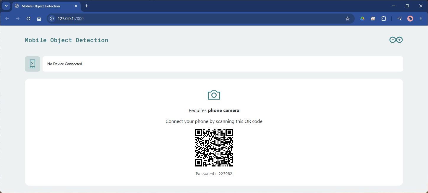
First start is the slow one: the vision Brick's container and model are fetched and provisioned. Open http://<your-board>.local:7000 and the Web UI Brick shows a pairing QR code. On your phone, open the Arduino IoT Remote app (signed into your Arduino Cloud account), scan the code, and tap Start streaming; the one-time code from the QR fills itself in, and the board's page switches to the live camera view with detection boxes. Now three things are alive at once, which is quietly remarkable when you list them: an AI inference pipeline against live video (MPU), a 50 Hz animation (MCU), and a web dashboard, all from one Run. Walk into frame and the lamp breathes up; walk out and, two seconds later, it fades.
The page you land on is the example's own dashboard, titled "Mobile Object Detection": a header, the live video with detection boxes, a confidence slider, and a running list of recent detections. That is expected -- we kept the smartphone example's assets/ wholesale and only repurposed what happens behind the detections (the lamp), so the web page still presents itself as the object-detection demo it shipped as. Renaming it, or paring it back to a bare presence indicator, is an assets/-editing exercise for another day.
Then run the experiment that justifies the architecture. SSH in and load the A53 cores (yes > /dev/null four times over, as in Part 1) while standing in view of the camera. The web view's frame rate sags; detections arrive later (your logs output timestamps them); the lamp does not flicker. Now imagine this project on a single-brain Linux board with the LED on a GPIO line, and you know exactly what the second brain is for. Same seam, same lesson as Part 1's twenty-line toy, now with a workload on each side that actually deserves its processor.
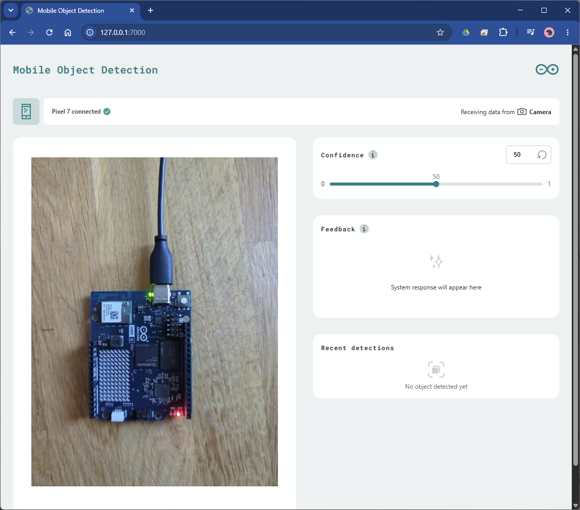
Expect the detection cadence itself to be a few inferences per second with the stock model, which for presence detection is ample. The end-to-end walk-in-to-lamp-on latency is dominated by the inference interval, not the Bridge (the RPC hop is milliseconds).
Troubleshooting
no camera found, and the App never finishes starting. The number-one smartphone-camera mistake: the App is built for a local camera. Confirmapp.yamlhasdevices: [remote_camera_0]under the vision Brick (not an empty Brick, and not a USB device id). Without it the Brick aborts provisioning before the web UI or QR ever appear -- so "no camera found" and "the QR never shows" are one and the same bug. (On the USB-webcam route, the same message instead means power: the hub must be a powered one, feeding the board 5 V/3 A while hosting the camera.)- The QR shows, but the phone won't pair or streams nothing. Three usual causes: you are not signed into Arduino Cloud in the IoT Remote app (the QR carries a one-time code, not credentials); phone and board are on different networks/subnets, or the Wi-Fi has "client isolation" enabled, so port 8080 is unreachable; or the App is not actually running (
arduino-app-cli app logs ...). - The web UI at
:7000does not load at all. Confirm the App is running, then try the board's raw IP instead of the.localname; mDNS is the first casualty on many home networks. - The page loads but is blank (no QR, no video). Your
assets/folder is the empty Web UI scaffold: view-source shows a bare<body>with<!-- Add your HTML here -->. The QR/video front-end lives in the smartphone example'sassets/(index.html,app.js,qrcode.min.js, theimg/folder); copy that folder into your App (or start from the example) and reload. Related:app.jspulls the video fromhttp://<hostname>:4912/embedusing the page's own hostname, so if you browse from another machine use the board's.local/IP, not127.0.0.1, or the video pane stays empty even after pairing. - Detections are erratic. Lower
confidenceand watch the raw stream in the logs before deciding the model is at fault: lighting and camera angle dominate. Raisedebounce_secif the A53s are working harder than the application needs. - The lamp reacts but never releases. Your hold-timeout path is not running: the classic cause is the Part 1 sin (
App.run()missing or the user loop replaced by a barewhile True), which silently removes the only code that reports absence. Bridge.callerrors in the Python logs. The sketch half is not up or not providing the function: check the sketch compiled (thelogscommand interleaves both halves; look for the MCU deployment messages) and that the provided name matches the called name exactly.
Video 3. The basic LED circuit connected to Pin 9 (PWM) of the UNO Q to the LED, current limiting resistor and back to GND. Note the smooth PWM fade in and out of the LED while the CPU is busy with the heavyweight AI task.
Video 4. A quick demonstration of the overall system where the LED pulses when a human (an online photo of me in this example) is visible in the mobile phone video stream. The random Windows wallpaper contains birds that are identified as the "Bird" class, but the LED does not react to this class.
Conclusion
- A Brick is a packaged service plus a Python client, joined to the same MessagePack-RPC star network as your sketch.
- The vision Brick reduces "run a model against a camera" to a constructor and a callback; your code's job is policy (thresholds, timeouts, what crosses the seam), and the correct thing to send across was one integer.
- The MCU half's discipline (RPC handler stores,
loop()renders) is what makes the lamp immune to inference load, and the stress test makes that immunity visible: it is the dual-brain argument, demonstrated. - Custom models are a menu action away (Edge Impulse
.eimfiles in App Lab's AI models tab), which turns this project into a template: person becomes cat (other animals apply equally!), lamp becomes cat-flap actuator, while the architecture remains unchanged.
The series so far has treated the UNO Q's software stack as given: App Lab above, Bricks beside, and a Zephyr-based Arduino core below, loading our sketches as ELF extensions. In the next part we lift that last lid: we will leave App Lab entirely, point west at the STM32U585, and put our own Zephyr firmware on the UNO Q's second brain, closing the loop with the XIAO nRF52840 series.