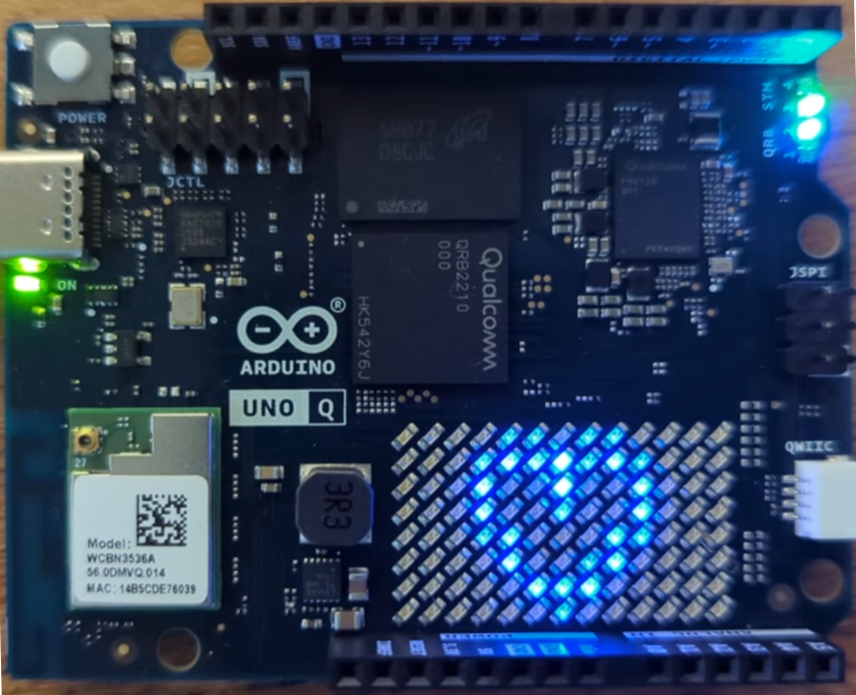
Getting to Know the Arduino UNO Q: Two Brains, One Board, and Zephyr Underneath
The Arduino UNO Q pairs a quad-core Linux processor with a real-time STM32 microcontroller on one UNO-shaped board, and quietly runs Zephyr where the classic Arduino runtime used to be. This guide takes an engineer's look at the architecture.

Getting to Know the Arduino UNO Q
To my mind, the Arduino UNO Q is the most architecturally interesting board Arduino has ever shipped, and the interest starts before you open the box. In late 2025 Qualcomm acquired Arduino, and the UNO Q is the first product of that pairing: the classic UNO footprint and header layout, but carrying a Qualcomm Dragonwing QRB2210 application processor running Debian Linux and an STM32U585 microcontroller for real-time work, wired together as one system. Arduino calls it a "dual brain" design. Readers of my BeagleBone books will recognise the philosophy immediately: it is the Linux-plus-real-time-unit pattern (think of the BeagleBone's PRUs, or the common Raspberry Pi + microcontroller pairings) productised into a €60-€80 class board with the (very) rough edges filed off.
setup() and loop() and never think about what sits underneath. It is a sophisticated multi-processor system: a full Debian Linux computer tied to a real-time microcontroller, with a remote procedure call layer stitching the two together. To get real value from it you need to be comfortable at a Linux command line (SSH, the filesystem, apt, processes) and willing to think about low-level, real-time programming on the microcontroller side. If neither of those is true for you yet, the board will still work, but much of what makes it interesting will stay out of reach, and an UNO R4 or a Raspberry Pi is the better place to start. This guide, and the series that follows, assumes you want to understand the whole system, not just the sketch.And there is a second, quieter piece of news inside it that this series cares about deeply: the Arduino runtime on the microcontroller side is now built on Zephyr. When you upload a sketch to the UNO Q you are, whether you know it or not, deploying code into a Zephyr RTOS system. For readers of the previous blogs, who have hand-written Zephyr's prj.conf files and partition maps, the UNO Q offers a nice feature: watching the same machinery set up for a mass-market audience, and understanding exactly what the workflow hides.
This guide covers the architecture properly, gets the board to first boot, explains how a sketch actually executes now (the answer has changed more than at any point in Arduino's twenty-year history), and finishes with a small but genuinely dual-brain application: Linux measures, the microcontroller acts, and the division of labour is the important education lesson.
The two brains, properly introduced
| MPU: Qualcomm Dragonwing QRB2210 | MCU: STMicroelectronics STM32U585 | |
|---|---|---|
| Cores | 4x Arm Cortex-A53 @ up to 2.0 GHz | 1x Arm Cortex-M33 @ 160 MHz |
| Memory | 2 GB or 4 GB LPDDR4 | 786 KB SRAM |
| Storage | 16 GB or 32 GB eMMC | 2 MB flash |
| Operating system | Debian Linux | Zephyr RTOS |
| You program it in | Python (primarily) | C++ (Arduino sketches) |
| Extras | Adreno GPU, dual ISPs, Wi-Fi 5, BT 5.1 | TrustZone, rich analogue + timers |
| Its job | Networking, storage, AI models, UIs | Pins, timing, the physical world |
(The bold entries are the 4 GB/32 GB variant this guide is written against; a 2 GB/16 GB variant is the entry model.)
The two processors are not neighbours that simply share a PCB; they are wired as a system. The MCU owns the UNO shield headers, the analogue pins, the 8×13 blue LED matrix, and shares four user RGB LEDs with the system, so anything with tight timing or electrical reality lives on the Cortex-M33. The MPU owns the network, the USB-C port (which does DisplayPort output: this board can be a small Linux desktop), the cameras via its ISPs, and the storage. Between them runs a serial link carrying a remote procedure call protocol, which a later section makes concrete.
What Arduino provides: the schematics and the Gerber files (the intermediate files a fabrication house uses to physically print the bare board) are released under a CC BY-SA 4.0 licence, alongside the datasheet, pinout, and STEP files for mechanical fit.
What is missing: the native, editable CAD design files. You get the final "baked" manufacturing outputs rather than the editable project a PCB tool could reopen, so redrawing the layout or reusing a section of the board in your own design is difficult. That omission is precisely why it fails the OSHWA definition, which requires the design files in the preferred format for making changes. Separately, the dual-brain architecture leans on the Qualcomm QRB2210, which needs proprietary, closed-source firmware "blobs" to boot at all, so the software stack is not fully open either.
Where to find the files: the schematics, datasheet, and Gerbers are on the Arduino UNO Q hardware documentation page, under the Resources section. For a full outside analysis of the open-hardware question, see open-hardware advocate Michael Weinberg's write-up, Is the Arduino UNO Q Open Source Hardware?
The QRB2210, in more detail
The table's one-line summary undersells the Linux half, so it is worth pausing on what this chip actually is. The QRB2210 is the robotics-branded sibling of Qualcomm's QCM2290, an entry-tier smartphone SoC, and the QRB prefix (Qualcomm Robotics, now folded into the Dragonwing IoT brand) buys the things embedded products need that phones do not: industrial qualification and, crucially, long-term availability commitments. Before it turned up on an Arduino, this chip anchored Qualcomm's RB1 robotics development platform. That phone background is the right lens for reading the block diagram below, because it explains why a board in this price class arrives with silicon that hobbyist SBCs usually lack:
- A real camera pipeline. The Spectra 340L ISP sits behind two 4-lane MIPI CSI interfaces and can service two cameras at once: dual 13 MP or a single 25 MP sensor at 30 fps, with zero-shutter-lag capture, multi-frame noise reduction, and electronic image stabilisation done in hardware rather than on the CPU. Every phone needs this; almost no microcontroller-adjacent board has it. The UNO Q's camera story (part 2 of this series) rests on this block.
- A display pipeline, not just a framebuffer. The Adreno DPU 920 drives a 4-lane MIPI DSI interface at up to 1080p60, with the Adreno 702 GPU (845 MHz, OpenGL ES 3.1, Vulkan 1.1) rendering behind it. This is the silicon behind the UNO Q's display output on the USB-C connector, and the board doubling as a small Linux desktop.
- Hardware video codecs. The video engine encodes and decodes 1080p30 H.264 and H.265 without troubling the A53 cores, which matters the moment a project streams or records a camera.
- Radio on the die. The WLAN DAC/ADC blocks in the diagram are the phone background giveaway: Wi-Fi 5 and Bluetooth are integrated on the SoC itself (alongside an FM receiver, in case the phone heritage was not obvious enough), rather than hanging off a separate module as on a Raspberry Pi.
- A serial-port fabric. Ten QUP engines, each software-configurable as UART, I²C, SPI, or I3C, plus 102 GPIOs and another 27 in a low-power island. On the UNO Q most of this fabric is spent on the board itself (eMMC, the radio, USB, and the link to the STM32); the shield headers you actually solder to belong to the MCU, as the previous section explained.
Two caveats belong next to that list. First, there is no NPU: AI inference on this chip runs on the CPU and GPU, which is why the AI models you will meet in App Lab's Bricks are the small, quantised kind rather than anything server-class. Second, the Cortex-A53 is Arm's little efficiency core, a familiar face from mid-2010s phones and the Raspberry Pi 3, so a Pi 5's Cortex-A76 cores will comfortably outperform it. This chip's virtues are integration and frugality (the whole board runs from a 5 V USB-C supply with no heatsink in sight), not raw compute, and the positioning table at the end of this guide scores it accordingly.
One last thing to notice in the diagram: the "Processors" box does not stop at the A53s. There is an LPASS DSP for audio and sensor duties, and an RPM (a Cortex-M3 doing resource and power management) that Linux never shows you. "Dual brain" is almost marketing modesty; before the STM32 enters the picture, the QRB2210 is already several computers cooperating in one package, as described in Figure 1.
Qualcomm Dragonwing QRB2210
Peripherals
Processors
Air interfaces
Memory support
Multimedia
Adreno™ DPU 920
DSI
C-PHY 1.0
Communication Suite, HD
audio
Internal functions
Figure 1: block diagram of the Qualcomm Dragonwing QRB2210, showing the full I/O complement: the quad Cortex-A53 cluster and its supporting processors, the QUP serial fabric and GPIOs, the camera and display pipelines, and the on-die radio.
The STM32U585, in more detail
The microcontroller deserves the same treatment, because its part number undersells it too. The STM32U585 is not a budget part chosen to tick the "real-time" box: it belongs to ST's STM32U5 family, the company's flagship ultra-low-power line, launched in 2021 and aimed squarely at the secure, battery-conscious IoT devices that regulation increasingly demands. On a board whose other half runs Debian it is tempting to treat the MCU as the junior partner, but by microcontroller standards this is a senior chip, and the block diagram below gives the same guided tour:
- Memory that makes the loader model work. 2 MB of dual-bank flash and 786 KB of SRAM is a huge allocation by MCU standards (the classic UNO's ATmega328P had 2 KB of SRAM; this has nearly four hundred times that). The headroom matters architecturally: the precompiled Zephyr "loader" firmware and your sketch, delivered as a relocatable ELF, live side by side in this space, and the next section explains why that arrangement is the most interesting thing on the board.
- Analogue worth the headers. One 14-bit ADC sampling at up to 2.5 Msps plus a second 12-bit ADC, two 12-bit DACs, two op-amps with programmable gain, and two ultra-low-power comparators. The UNO measured the world at 10 bits; the pins in the same physical positions now resolve sixteen times finer, with signal conditioning on-die.
- Timers and maths at the pins. Two advanced control timers (the motor-drive kind, with complementary outputs and dead-time insertion), a spread of 16- and 32-bit general-purpose timers, four low-power timers, and CORDIC and FMAC accelerators for trigonometry and filtering. Control loops can run entirely at this end of the board, which is precisely the division of labour the UNO Q is built around.
- Security silicon. Beyond the Cortex-M33's Armv8-M TrustZone: AES-128/256, an elliptic-curve public-key accelerator, on-the-fly flash decryption (OTFDEC), a true random number generator, and tamper pins. The "8" in U585 is the flag that the cryptographic hardware is present (the U575 sibling omits it). The Arduino runtime does not use it today, but the chip was designed for PSA and SESIP security certification, and it is one reason this MCU will not look dated in five years.
- Ultra-low power, mostly latent here. Around 19.5 µA/MHz running and 110 nA in shutdown, with a feature ST calls LPBAM that lets DMA and peripherals keep sampling and timestamping while the core sleeps. On the UNO Q the Linux side dominates the power budget, so treat this as latent capability, but it is exactly what you want if this board leads you to design the same family into something battery-powered.
There is also a quiet compatibility story in the choice: the STM32U5 is a first-class Zephyr citizen (ST's B-U585I-IOT02A Discovery kit is a standard Zephyr and TrustedFirmware-M reference platform), which can hardly have been an accident when Arduino was selecting the chip to carry its Zephyr-based core. Part 3 of this series will drive this same silicon with west and vanilla Zephyr directly, at which point everything in Figure 2 stops being a spec sheet and becomes your API.
STMicroelectronics STM32U585
Core & memory
@ 160 MHz
Analogue
Timers
Connectivity
Security
Ultra-low power
Figure 2: block diagram of the STMicroelectronics STM32U585: an Armv8-M Cortex-M33 with unusually generous memory, certification-grade security hardware, a rich analogue and timer complement behind the UNO headers, and an ultra-low-power fabric the UNO Q holds in reserve.
services
(MessagePack-RPC)
'loader' firmware)
as an ELF extension
LEDs, ADC
Figure 3: the UNO Q as a system. Python and containerised services on Linux, a Zephyr-hosted Arduino core on the microcontroller, and an RPC router stitching them into one application.
Why build a board this way? Because the two halves are bad at each other's jobs, and every serious embedded Linux project eventually rediscovers this. Linux gives you Python, OpenCV, TensorFlow-class models, filesystems, and Wi-Fi, but it cannot promise that your code runs in a deterministic manner: a garbage collection pause or a busy scheduler between you and a stepper motor is how projects fail. A microcontroller keeps promises measured in microseconds but would spend all its RAM opening one HTTPS connection. The classic RPi answer is two boards and a USB or uart cable; the UNO Q's answer is one board where the pairing is designed, powered, and (the actually novel part) programmed as a single unit.
On the Linux side, the 2.0 GHz A53s are enormously fast on average, but Debian is engineered for throughput and fairness, not punctuality. Between your Python statement and a pin wiggle sit a pre-emptive scheduler juggling dozens of processes, virtual memory, caches, power-state changes, and the garbage collector, and any of them may insert a pause of microseconds or, occasionally, tens of milliseconds. No single delay is likely; over hours of running, one is close to certain, and you cannot schedule when it lands. (A
PREEMPT_RT kernel narrows the tail; it does not eliminate the machinery that causes it.)On the MCU side, the 160 MHz Cortex-M33 is hundreds of times slower on paper, yet Zephyr schedules a handful of known threads by fixed priority, there is no virtual memory or swapping, and interrupt latency is a fixed count of clock cycles you can look up. When the sketch says
delay(500), the LED changes in 500 ms every time, forever, regardless of what Linux is doing a few millimetres away. That is why the system-pulse demo's heartbeat stays rock steady while the A53s are saturated: determinism is not about being fast, it is about being on time, and it is a property you buy with architecture, not clock speed.For two decades, "uploading a sketch" meant compiling your code together with the Arduino core into one firmware binary and burning the whole thing into flash. On the UNO Q (and Arduino's other new-generation boards) that model is gone, and what replaced it is worth an expert's attention.
The background: Arduino's previous professional core was built on Arm's Mbed OS, which reaches end of life in July 2026. Arduino chose Zephyr as the successor and has been building ArduinoCore-zephyr in the open. It is not a port in the old sense; it changes the execution model:
- The board runs a precompiled Zephyr firmware that Arduino calls the "loader": the Zephyr kernel, the drivers, the network of subsystems, and the Arduino core API implementation, built once by Arduino and flashed to the MCU like any Zephyr application (it is a sibling of what we built by hand throughout the previous series: somewhere in Arduino's CI there is a
prj.conf). - Your sketch compiles not into a firmware image but into a small relocatable ELF file, and the loader brings it to life at runtime using Zephyr's LLEXT (Linkable Loadable Extensions) subsystem, resolving the sketch's calls to
digitalWriteand others against symbols the loader exports. - Uploading a new sketch therefore means shipping a small ELF to the loader, not reflashing the chip. Iteration is faster, and the sketch is decoupled from the system firmware underneath it.
digitalWrite are left as unresolved symbol references, the loader can drop the sketch anywhere in free memory and stitch it to the running firmware at load time, exactly as Linux does when it loads a shared library (.so) into a program that is already running.If you have followed the earlier series, the right mental model is: the loader is the zephyr.uf2 and your sketch is a plug-in. It is the same trick a Linux kernel plays with modules, on a 160 MHz Cortex-M33. You can even see the seam in the tooling: the UNO Q's fully qualified board name in the Arduino toolchain is arduino:zephyr:unoq, with Zephyr named in the middle.
This means the sketch environment can be supervised. On the UNO Q the Linux side manages the MCU (deploying sketches, restarting them, pairing them with Python code), which is only possible because a sketch is now a loadable artefact rather than the whole firmware. That supervision is what App Lab builds on. It also means that when you eventually outgrow the Arduino API, the full Zephyr underneath is not a different world; part 3 of this series will target the same M33 with west directly.
App Lab and the anatomy of an "App"
Arduino App Lab is the development environment for this board, and it reframes what you build. You do not write "a sketch" or "a Python script"; you write an App, which is a folder containing both, plus a manifest that tells the system how they fit together. This is the general form:
my_app/
├── app.yaml              # manifest: name, what to run where
├── python/
│   ├── main.py           # runs on the MPU (Debian)
│   └── requirements.txt  # pip dependencies, installed for you
└── sketch/
    ├── sketch.ino        # runs on the MCU (Zephyr)
    └── sketch.yaml       # build settings (the arduino:zephyr:unoq FQBN)
Start the App and the system does the rest: builds the sketch, loads it onto the MCU, starts your Python, and connects the two. Stop it and both halves stop. This is the "programmed as a single unit" promise: the unit of deployment spans both processors.
Two more App Lab concepts deserve a mention now:
- Bricks are pre-packaged capabilities for the Linux side (vision models, audio, web dashboards) that an App can declare and use from Python. They are how "detect a person and fire an output pin" becomes a realisable project; part 2 of this series will use them properly.
- The Router (Bridge) is the RPC mechanism joining the halves: an arduino-router service using MessagePack-RPC in a star topology, with clients (your Python, your sketch, Bricks) registering named functions that any other client can call. The API surface is small, as the demo will show:
Bridge.provide("name", fn)on one side,Bridge.call("name", args)on the other.
You can run App Lab in two ways, and the choice is surprising: on your PC (it connects to the board over the network), or on the board, because a computer with a quad-core CPU, 4 GB of RAM, and DisplayPort out does not need your PC. Plug a monitor into the USB-C port (via a PD hub so the board still gets its 5 V/3 A), add a keyboard, and the UNO Q is a small Linux desktop that develops for itself. For this guide I will assume the more conventional PC route and SSH.
sudo poweroff (or sudo shutdown -h now) syncs and unmounts everything before halting, after which it is safe to remove the cable; use sudo reboot when you only need to restart.First boot
- Power the board from a decent USB-C supply (it wants up to 5 V/3 A; a laptop port is fine for the headless use here. As with the Raspberry Pi, a weak charger is the classic source of mystery resets).
- On first boot, follow Arduino's current onboarding flow (App Lab on your PC discovers the board, or the board broadcasts a setup access point; the user manual tracks the current procedure) to hand it your Wi-Fi credentials. Download App Lab from: https://www.arduino.cc/en/software/#app-lab-section
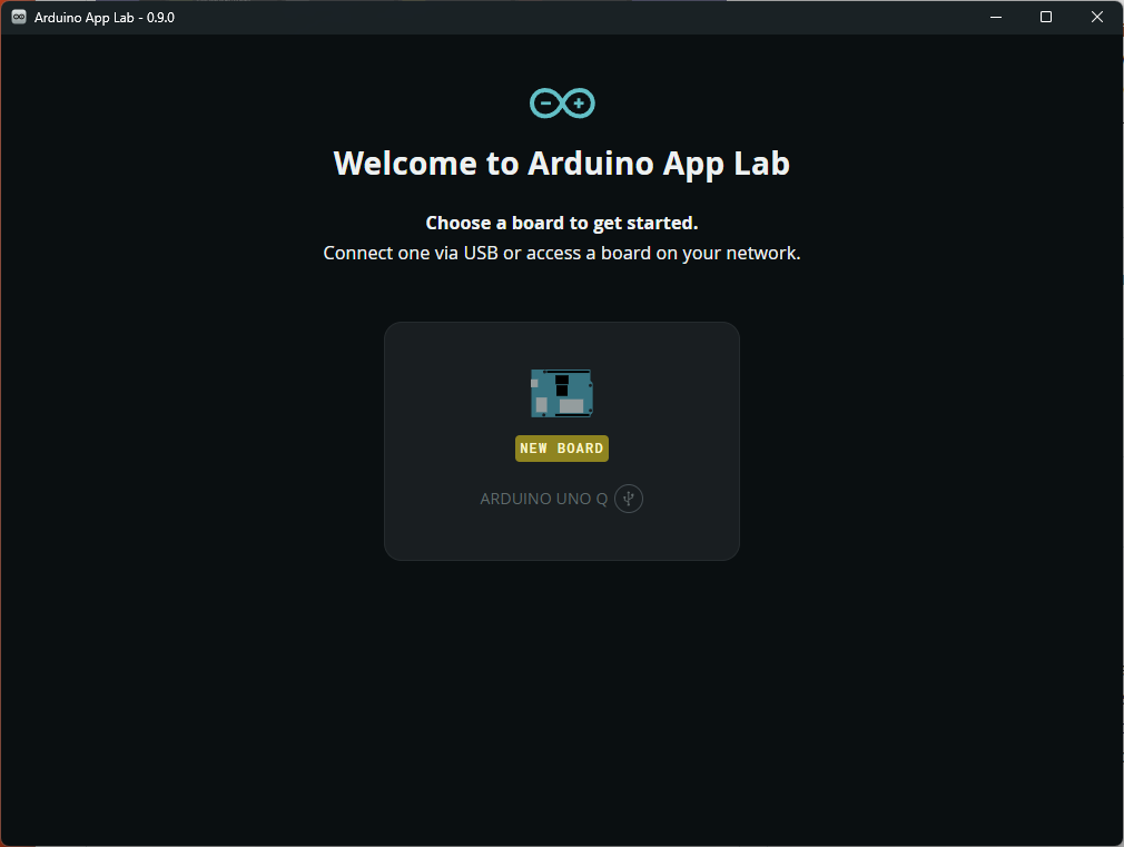
Reset the board if you cannot connect to it. Configure the board name, Wi-Fi details and username, then install updates. Updates can take quite some time!
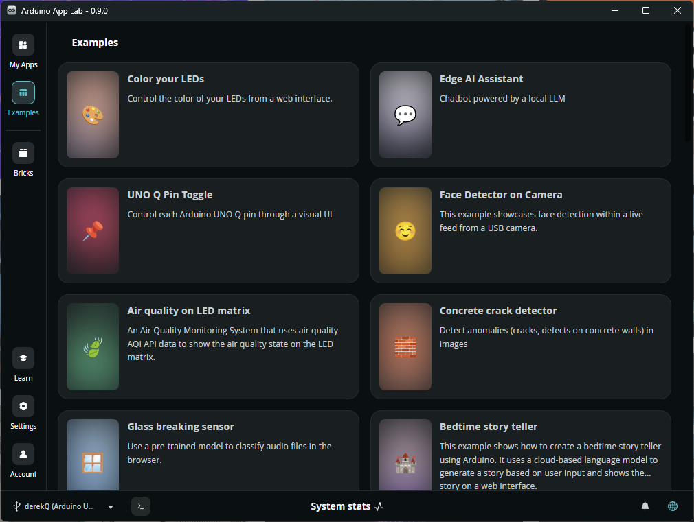
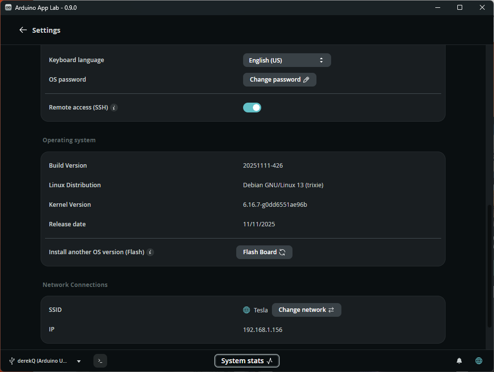
- Once it is on your network, you have a Debian machine. The board runs SSH out of the box with a default
arduinouser:
PS C:\Users\Derek Molloy> del "C:\Users\Derek Molloy\.ssh\known_hosts"
PS C:\Users\Derek Molloy> ssh arduino@192.168.1.156
The authenticity of host '192.168.1.156 (192.168.1.156)' can't be established.
ED25519 key fingerprint is ...
Are you sure you want to continue connecting (yes/no/[fingerprint])? yes
Warning: Permanently added '192.168.1.156' (ED25519) to the list of known hosts.
arduino@192.168.1.156's password:
Linux DerekQ 7.0.0-g122c2c22d838 #1 SMP PREEMPT Tue May 19 15:08:13 UTC 2026 aarch64
...
Debian GNU/Linux comes with ABSOLUTELY NO WARRANTY, to the extent
permitted by applicable law.
arduino@DerekQ:~$ uname -a
Linux DerekQ 7.0.0-g122c2c22d838 #1 SMP PREEMPT Tue May 19 15:08:13 UTC 2026 aarch64 GNU/Linux
arduino@DerekQ:~$ df -h
Filesystem       Size  Used Avail Use% Mounted on
udev             1.7G     0  1.7G   0% /dev
tmpfs            367M  1.7M  366M   1% /run
/dev/mmcblk0p68  9.8G  6.4G  2.9G  69% /
tmpfs            1.8G   12K  1.8G   1% /dev/shm
efivarfs         128K  2.2K  126K   2% /sys/firmware/efi/efivars
tmpfs            5.0M  8.0K  5.0M   1% /run/lock
tmpfs            1.8G  2.2M  1.8G   1% /tmp
tmpfs            1.0M     0  1.0M   0% /run/credentials/systemd-journald.service
/dev/mmcblk0p69   18G  621M   17G   4% /home/arduino
/dev/mmcblk0p67  488M  135M  353M  28% /boot/efi
tmpfs            367M   52K  367M   1% /run/user/103
tmpfs            1.0M     0  1.0M   0% /run/credentials/getty@tty1.service
tmpfs            1.0M     0  1.0M   0% /run/credentials/serial-getty@ttyMSM0.service
tmpfs            367M   48K  367M   1% /run/user/1000
arduino@DerekQ:~$ htop
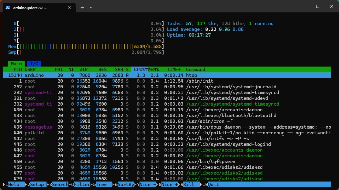
Take a moment with that prompt. Every board in my previous series was a device you reached from a computer; this one is a computer. htop shows four A53 cores; df -h shows a 32 GB filesystem; apt works. The microcontroller from the earlier guides is still here too, sitting on the other end of a serial link, running Zephyr, waiting to be given a sketch.
The App Lab experience also has a command-line twin on the board itself, which suits this audience and, usefully, makes the demo below scriptable:
arduino@DerekQ:~$ arduino-cli version
arduino-cli  Version: 1.5.1 Commit: 01f3d4f2b Date: 2026-06-05T10:22:11Z
arduino@DerekQ:~$ arduino-app-cli version
Arduino App CLI version 0.12.1
daemon version: 0.12.1
arduino-cli versus arduino-app-cli: they are not the same tool. You will see both on the board, and the distinction is exactly the "single unit spans both processors" idea made concrete on the command line.arduino-cli is the long-standing, general-purpose Arduino command-line tool, the same one the Arduino IDE drives under the hood on every board. Its unit of work is a sketch: it manages cores, libraries, and boards, then compiles and uploads to a single target. On the UNO Q it knows only the MCU half, addressed by the arduino:zephyr:unoq Fully Qualified Board Name (FQBN) we met earlier; it has no notion of Linux, Python, or Bricks.arduino-app-cli is the UNO Q's own tool, and its unit of work is an App, the folder holding both halves plus its manifest. Starting an App orchestrates the whole dual-brain dance: it builds the sketch (leaning on the Arduino core arduino-cli provides), loads it onto the MCU, installs the Python dependencies and any Bricks, launches your Python on Linux, and wires the two together through the router. One command supervises both processors at once.The rule of thumb: reach for
arduino-cli when you are thinking about the microcontroller alone, and arduino-app-cli when you mean the whole application. This guide uses arduino-app-cli throughout, because everything interesting here is dual-brain.These are the commands we will use in this blog entry:
arduino-app-cli app start ~/ArduinoApps/system_pulse     # build both halves, deploy, run
arduino-app-cli app logs  ~/ArduinoApps/system_pulse     # both halves' output, interleaved
arduino-app-cli app stop  ~/ArduinoApps/system_pulse
The first App: a system pulse
Blinking an LED is compulsory, but on a dual-brain board a plain blink would waste the second brain. So here is the smallest App I could design that is really dual: the LED blinks at a rate set by the Linux side's CPU load. Python (which can know the system load trivially) measures; the MCU (which can keep time without jitter) blinks. Idle board, lazy heartbeat; make Linux sweat and the pulse races. The total code is about twenty meaningful lines across both processors.
Create a new App in App Lab (or copy an example's folder structure over SSH) named system_pulse, and fill in the two programs.
arduino-router service introduced earlier: a remote procedure call (RPC) link that lets code on one processor call a named function living on the other, with the arguments serialised (as MessagePack), pushed across the internal serial link, and handed to the far side, all invisibly. You never touch a byte of the transport; you register functions by name and call them by name.This demo uses exactly one such function,
set_pulse. The Zephyr sketch on the MCU provides it, Bridge.provide("set_pulse", set_pulse), announcing to the router "I own a function called set_pulse, call it and I will run it." The Python on Linux calls it once a second, Bridge.call("set_pulse", period_ms), passing a single integer: the blink half-period in milliseconds it has just computed from the CPU load. That integer is the entire conversation between the two brains. Measurement happens on Linux, the number crosses the Bridge, and timing happens on the MCU. Watch for the matching provide/call pair as you read the two files below; everything else is ordinary Python and ordinary Arduino.The Linux half (python/main.py)
# system_pulse -- MPU half.
# Reads the 1-minute load average once a second and tells the MCU how
# fast to blink. Linux knows things; the MCU does things.

import time
from arduino.app_utils import *

def loop():
    with open("/proc/loadavg") as f:
        load1 = float(f.read().split()[0])

    # Map load to a blink half-period: 0.0 load -> 1000 ms (calm),
    # 4.0+ load (all four A53 cores busy) -> 200 ms (agitated).
    period_ms = int(max(200, 1000 - (load1 / 4.0) * 800))

    Bridge.call("set_pulse", period_ms)
    time.sleep(1)

# App.run() hands control to the App Lab runtime, which invokes loop()
# repeatedly and keeps the Bridge connection alive. Forgetting this line
# is the classic first-App error: the Python process ends immediately
# and the deployment fails with an unhelpful EOF.
App.run(user_loop=loop)
The Zephyr half (sketch/sketch.ino)
// system_pulse -- MCU half.
// Provides one remotely callable function and spends the rest of its
// life blinking with microcontroller-grade punctuality. This sketch is
// compiled to a relocatable ELF and loaded by the Zephyr-based Arduino
// core at runtime -- no full reflash, just a new extension.

#include "Arduino_RouterBridge.h"

static volatile uint32_t half_period_ms = 1000;

void set_pulse(int period_ms) {
    // Called from the Linux side via the Bridge (MessagePack-RPC over
    // the inter-processor serial link).
    half_period_ms = (uint32_t)period_ms;
}

void setup() {
    pinMode(LED_BUILTIN, OUTPUT);
    Bridge.begin();
    Bridge.provide("set_pulse", set_pulse);
}

void loop() {
    digitalWrite(LED_BUILTIN, HIGH);
    delay(half_period_ms);
    digitalWrite(LED_BUILTIN, LOW);
    delay(half_period_ms);
}
volatile, and why it is enough. The declaration static volatile uint32_t half_period_ms is doing quiet but real work. set_pulse does not run inside loop(); the Bridge invokes it on one of its own threads whenever a call arrives from Linux, so the variable is shared between two threads of execution. volatile tells the compiler the value can change behind the running thread's back, forcing it to re-read the variable from memory each time round loop() rather than cache a stale copy in a register. And because half_period_ms is a single 32-bit word, aligned, on a 32-bit core, each read and each write completes in one instruction, so loop() can never catch a half-updated value. That atomicity is why the demo needs no lock. Widen the shared state to a 64-bit type or a multi-field struct and that free safety disappears; you would then reach for one of Zephyr's locking primitives (a mutex or an atomic) to share it correctly. Volatile and other such concepts are described in detail in my interactive book https://book.derekmolloy.ie/ on edge programming.Those are the two programs, but remember from the App anatomy above that an App is four files: each half also carries a small manifest. Rather than hand-write those manifests, let the CLI scaffold a correct skeleton and then drop your two programs into it:
arduino@DerekQ:~$ cd ~/ArduinoApps
arduino@DerekQ:~/ArduinoApps$ arduino-app-cli app new system_pulse    # scaffolds app.yaml, python/, sketch/
arduino@DerekQ:~/ArduinoApps$ cd system_pulse
arduino@DerekQ:~/ArduinoApps/system_pulse$ nano python/main.py        # replace the stub with the Python half above
arduino@DerekQ:~/ArduinoApps/system_pulse$ nano sketch/sketch.ino     # replace the stub with the sketch above
The folder name must match the name you start the App with later, which is why we call it system_pulse. Scaffolding is important on the sketch side: the sketch manifest is not a one-line FQBN but a named build profile, and that profile is the part the arduino:zephyr platform insists on. Skip it (or write only a bare default_fqbn) and arduino-app-cli app start fails with "sketch has no default profile". What app new writes is deliberately spare, with an empty libraries: list ($ more sketch/sketch.yaml):
profiles:
  default:
    platforms:
      - platform: arduino:zephyr
    libraries:
default_profile: default
The app.yaml on the Linux side is simpler, naming the App for the runtime ($ more app.yaml):
# app.yaml: The main configuration file for your Arduino App.
# This file describes the application's metadata and properties.

# The user-visible name of the application.
name: system_pulse
# The icon for the application, can be an emoji or a short string.
icon:
# A list of network ports that the application exposes.
# Example: [80, 443]
ports: []
# A list of bricks used by this application.
bricks: []
Notice what is not there – you do not list the Bridge libraries yourself. The first time you run arduino-app-cli app start, the tooling resolves and adds them for you, and Arduino_RouterBridge, MsgPack, and their dependencies scroll past in the start log a little further down, pulled at whatever versions ship with your installed arduino:zephyr core. The resolved build is cached in a .cache directory the tool creates inside the project (which is why the folder grows after the first run); treat it as build output and add it to .gitignore if you keep the App under version control. If you would rather author the files on your PC, scp -r system_pulse arduino@<the-board's-IP>:~/ArduinoApps/ copies the whole folder across, and creating the App in App Lab scaffolds the same skeleton for you.
All going well, at this point you should have:
arduino@DerekQ:~/ArduinoApps$ tree -F system_pulse/
system_pulse//
├── app.yaml
├── python/
│   └── main.py
├── README.md
└── sketch/
    ├── sketch.ino
    └── sketch.yaml

3 directories, 5 files
Run it, then prove the point
Start the App from App Lab, or over SSH:
arduino@DerekQ:~/ArduinoApps$ arduino-app-cli app start ~/ArduinoApps/system_pulse
[INFO] Starting app "system_pulse"
Progress[preparing]: 0%
Progress[sketch compiling and uploading]: 0%
[INFO] Sketch profile configured: Name="default", Port=""
[INFO] The library Arduino_RouterBridge has been added from sketch project.
[INFO] The library Arduino_RPClite has been added from sketch project.
[INFO] The library MsgPack has been added from sketch project.
[INFO] The library DebugLog has been added from sketch project.
[INFO] The library ArxTypeTraits has been added from sketch project.
[INFO] The library ArxContainer has been added from sketch project.
...
<<<Takes a bit of time at this point!>>>
...
Progress[]: 100%
✓ App "system_pulse" started successfully
arduino@DerekQ:~/ArduinoApps$
Interestingly, you will see the following in your Arduino App Lab window:
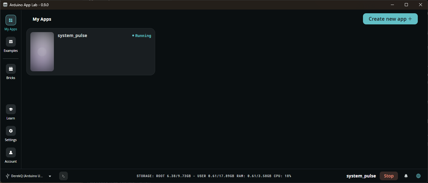
arduino-app-cli app logs. A dual-brain App has two streams of output, and the CLI interleaves them for you. In a spare SSH session, run arduino-app-cli app logs ~/ArduinoApps/system_pulse and you will see the Python side and the sketch side together, in the order things actually happened. This is the single most useful debugging habit on this board: when an App appears to "do nothing", the logs almost always reveal which half failed, whether the Bridge connected, and whether set_pulse is being called. Anything your Python prints, or the sketch writes with Serial.print, surfaces here.After about one minute, the user LED settles into a roughly once-per-second heartbeat. Now open a second SSH session and give the A53 cores something to do:
arduino@DerekQ:~$ yes > /dev/null & yes > /dev/null & yes > /dev/null &
[1] 2549
[2] 2550
[3] 2551
arduino@DerekQ:~$ sleep 60; kill %1 %2 %3
arduino@DerekQ:~$
In the first terminal window, you can use htop to display the current load:
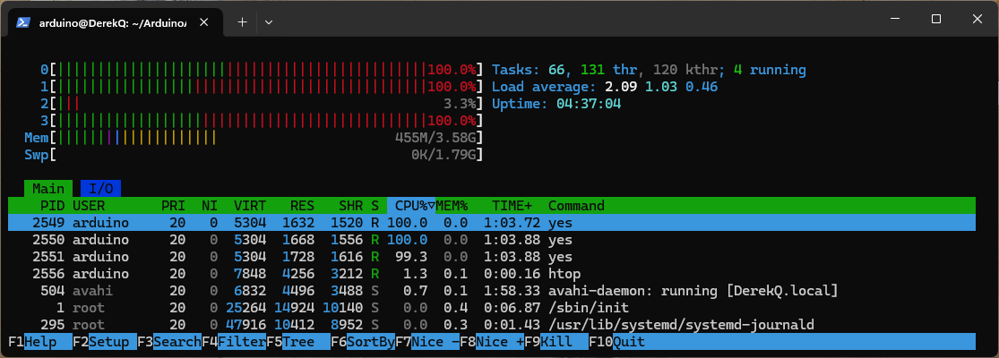
yes is a tiny Unix utility that prints its argument (or y by default) over and over, as fast as the CPU will let it, forever; redirecting it to > /dev/null throws the output away so all that is left is the work of generating it, which pins one core at 100%. The trailing & puts each one in the background so the shell returns immediately, and running three of them (the board has four A53 cores) drives the load average up hard without freezing your session. The shell prints a job number and process ID for each ([1] 2549 and so on); sleep 60; kill %1 %2 %3 then waits a minute and stops all three by job number, so the load is a controlled 60-second burst rather than something you have to chase down by hand.htop, running in the other terminal, is the interactive version of the classic top: a live, colour-coded view of the system. The four per-core meters across the top are the ones to watch here, filling as the yes processes take effect; below them a memory bar and the load-average figure (the same number /proc/loadavg feeds to our Python), and then a sortable list of processes where the three yes jobs sit at the head, each near 100%. It is the human-friendly way to see the load our LED is quietly reporting. Press q to quit, or F10. (If htop is not installed, sudo apt install htop, or fall back to top.)Over the next minute, as the load average climbs, the heartbeat visibly quickens; kill the load and it relaxes again. It is a toy example, but notice what it demonstrates that neither classic Arduino nor a bare Raspberry Pi can show this cleanly:
- The measurement belongs on Linux.
/proc/loadavgis oneopen()away in Python; a microcontroller has no notion of it. - The timekeeping belongs on the MCU. The blink is steady even while the CPUs are saturated, precisely because nothing about the blink depends on Linux being responsive. Try implementing the same demo purely on the Linux side (GPIO from Python) and watch the heartbeat stutter under the very load it is supposed to display.
- The seam is one function call.
Bridge.provideon one side,Bridge.callon the other; the router, the serialisation, the serial link, and the process supervision are all someone else's carefully maintained problem.
That reasoning, this job goes here because of what this processor is, is the entire discipline of heterogeneous system design, in twenty lines. Part 2 will apply it to something worth keeping: sensor capture on the MCU, an AI Brick and a web dashboard on the MPU.
LED_BUILTIN deliberately: it is the same on every board you have ever owned, and the point here is the architecture, not the peripheral./sys/class/thermal/thermal_zone0/temp (it reports millidegrees Celsius, so divide by 1000) instead of the load average, and let the pulse quicken as the board warms. (2) Change the feel. Replace the linear load-to-period mapping with a steeper curve, or invert it so a busy board calms rather than races; this is pure Python and needs no reflash of the sketch. (3) Prove the supervision. Run arduino-app-cli app stop ~/ArduinoApps/system_pulse and watch both halves stop together, the LED going dark as the Python exits, then start it again and watch them come back as one unit.Where it sits: a positioning note
| Classic UNO / UNO R4 | Raspberry Pi 5 | UNO Q | |
|---|---|---|---|
| Real-time I/O | Excellent, it is all it does | Poor from userspace | Excellent (MCU side) |
| Linux, Python, AI | No | Excellent | Yes (MPU side) |
| The two together | No | Only with an add-on MCU | Designed in, one toolchain |
| Shield ecosystem | Yes | No | Yes (UNO headers on the MCU) |
| What you learn | Microcontrollers | Linux | The seam between them |
That last row is my view of the suitability of this board in education. Individually, neither half is the best of its kind: a Pi 5 out-muscles the MPU and a bare STM32 board is cheaper than the MCU. Together, programmed as one App, they teach the thing that neither teaches alone, which also happens to be the shape of many real-world embedded products emerging this decade.
What that shape looks like in the field. The "measure where it is easy, act where timing is guaranteed" split is not a teaching contrivance; it is the architecture underneath a great many real products. In each of the following, picture the Linux half owning the network stack, the heavy computation and the user-facing application, and the Zephyr half owning the microsecond-accurate loop that actually touches the world:
- Self-balancing and legged robots. Linux runs the vision, navigation and remote control; the MCU closes the balance loop, reading the IMU and driving the motors at a fixed kHz rate that a single Linux scheduler pause would topple. The inverted pendulum is a real-time problem, and it is the canonical demonstration of why the second brain exists.
- Physical AI and camera-guided actuation. A model on Linux (an App Lab Brick, or your own) decides what to do from a camera or microphone; the MCU does it deterministically, driving servos, a gripper or a pan-tilt head. This is the presence lamp of Part 2 grown up into pick-and-place, parcel sorting, or a face-following gantry.
- Motion control: CNC machines, 3D printers, plotters. The MCU emits step-and-direction pulses with timing too tight to entrust to an operating system, while Linux runs the job queue, the G-code or slicer front end, and the web dashboard. This is precisely how modern host-plus-MCU printer firmware is already split.
- mmWave radar, lidar and sensor fusion. The MCU ingests a high-rate sensor stream with steady timing (the 24 GHz radar of parts 4 and 5 is exactly this); Linux does the tracking, the classification and the dashboard. Presence detection, people counting and fall detection all live in this pattern.
- Motor and power-electronics control. Field-oriented motor drive, or a switching converter using the STM32's advanced-control timers and dead-time insertion, runs on the MCU; Linux handles telemetry, tuning, MQTT and the cloud. Think robot joints, e-bike drives, solar inverters and battery-management systems.
- Instrumentation and edge data acquisition. The MCU samples the 14-bit ADC on a hard schedule and generates precise triggers or waveforms on the DACs; Linux buffers the data, runs anomaly detection or logging, and streams results upstream, the shape of a predictive-maintenance node.
The common thread is a division no single-processor board draws cleanly: a rich, connected, occasionally-late application layer sitting over a small, dependable, always-on-time control layer, with one App spanning both.
Conclusion
- The UNO Q is a genuine heterogeneous system in a €60-€80 UNO form factor: quad-core Debian Linux (Dragonwing QRB2210) plus a real-time STM32U585, with the pairing designed and supervised rather than improvised.
- Zephyr is the quiet headline: the Arduino core on the MCU is a precompiled Zephyr firmware that loads your sketch as a relocatable ELF via LLEXT, a fundamental change to what "uploading a sketch" means and a bridge (Part 3 will cross it) to programming the same chip with Zephyr directly.
- An App spans both processors: Python and sketch in one folder, deployed and run as a unit, talking through a MessagePack-RPC Bridge whose API is two functions.
- The system-pulse demo is deliberately tiny, but its design argument (measure where measuring is easy, act where timing is guaranteed) is the whole discipline this board exists to teach.
In the next part of this series we develop a real application with hardware on the MCU headers, an AI Brick doing the clever bit on Linux, and a web UI, all inside one App. After that we will lift the Arduino lid entirely and put our own Zephyr on the Cortex-M33, closing the loop with the previous series.

