
Under the Hood of the Arduino UNO Q: Vanilla Zephyr on the Cortex-M33
Part three of the UNO Q series removes the App Lab, Arduino core, sketch loader and just uses west, a devicetree, and our own Zephyr firmware on the board's STM32U585, driving the 13x8 LED matrix through Zephyr's display API with grayscale functionality.

Vanilla Zephyr on the UNO Q Cortex-M33
This article is part 3 of a series on the Arduino UNO Q:
1. Getting to know the UNO Q: two brains, one board, and Zephyr underneath
2. A real application: an AI Brick, a camera, and a presence lamp
3. This guide: vanilla Zephyr, straight onto the STM32U585
This part goes as deep into the board as the series gets. Later parts climb back up to build real applications on top of what we find here, so if you would rather see the board used than dismantled, this is the one to skip.
It also picks up the thread of my XIAO nRF52840 Zephyr series: the samewest buildworkflow from that series, pointed at Arduino's newest board.
Part 1 of this series made a claim that this part exists to prove: that underneath the Arduino UNO Q's sketch experience sits a real Zephyr RTOS, and that the path from App Lab down to bare metal is possible. So far we have focused on sketches loaded as ELF extensions into Arduino's Zephyr-based core, orchestrated by App Lab, talking to Linux through the Bridge. Here we look at the No App Lab, no Arduino core, no loader option. We point west at the STM32U585 and put our own firmware on it, exactly as my XIAO series did for the nRF52840.
Two discoveries make this far more interesting than I expected. First, the UNO Q is in mainline Zephyr (boards/arduino/uno_q, board target arduino_uno_q): the device tree describing its LEDs, its die-temperature sensor, and interestingly, its 13×8 LED matrix is maintained upstream, some of it by Qualcomm engineers, and a current Zephyr workspace like the one from my XIAO series builds for it out of the box. Second, the debug probe is already on the board: the Qualcomm MPU can act as a CMSIS-DAP adapter for the STM32, so the SWD probe I told XIAO readers to buy is, here, a Linux process and an adb command. Importantly, the whole exercise is reversible to the Arduino ecosystem with one documented command, so nothing about your App Lab setup is at risk beyond a re-flash.
The application is a comet sweeping the LED matrix with a fading grayscale tail, using a capability of the matrix hardware that the Arduino layer's API doesn't present. Below the abstraction layer is where the hardware's full feature set lives and is worth exploring.
Video 1. The final outcome of this article -- a custom comet effect lighting pattern using Zephyr running on the MPU only with no use of the CPU.
arduino_uno_q board will do) with the Zephyr SDK 1.0.1. The board port is new and actively developed: check boards/arduino/uno_q/doc in your tree for changes, particularly around west flash support, which at the time of writing is not yet wired to the on-board debug adapter.A tour of the board port
Before writing any code, spend a few minutes reading what Arduino and Qualcomm upstreamed, because the devicetree is the software datasheet of what the MCU side really owns. Highlights from boards/arduino/uno_q/arduino_uno_q-common.dtsi:
- Two user RGB LEDs (LED3 and LED4 on the board's four-LED strip; the other two belong to the Linux side), active-low on port H, with
led0aliased to LED3's green channel. The devicetree hides the active-low inversion, exactly as it did on the XIAO. - The die-temperature sensor (
die-temp0alias): readers of my C++ post will see the exact same two-call sensor API pattern that read the nRF52840's die there reads the STM32U585's die here. We will print it, purely to prove that Zephyr allows the writing of identical application code against different silicon. - The full analogue and digital complement of the UNO R3 headers: six ADC channels at 14-bit, the DAC, I2C, SPI (including the ICSP header routing, noted in comments), so classic shield work is fully open from vanilla Zephyr.
- Two UARTs, with quite different jobs.
usart1(PB6/PB7, 115200) is what the devicetree nameszephyr,console, and following those pins is instructive:arduino_r3_connector.dtsimapsD1 -> PB6andD0 -> PB7and labels the peripheralarduino_serial, so the console emerges on the Arduino header, exactly where a classic Uno has always put its serial port.lpuart1(PG5-PG8, and the only one with RTS/CTS hardware flow control) has no header pins at all and is the internal link to the Qualcomm MPU: that is the Bridge from Parts 1 and 2. - An MCUboot-shaped partition table (64 KB boot, two 416 KB slots, 128 KB storage): present but opt-in. Our build ignores it and links at address zero, owning the whole 2 MB; readers of my MCUboot post will recognise every label in that table and could resurrect the whole OTA machinery here as an exercise.
PS C:\zephyr> .\zephyrproject\.venv\Scripts\Activate.ps1
(.venv) PS C:\zephyr> cd .\zephyrproject\zephyr\boards\arduino\uno_q\
(.venv) PS C:\zephyr\zephyrproject\zephyr\boards\arduino\uno_q> dir
    Directory: C:\zephyr\zephyrproject\zephyr\boards\arduino\uno_q
Mode                 LastWriteTime         Length Name
----                 -------------         ------ ----
d-----        02/07/2026     19:48                doc
-a----        02/07/2026     19:48           1307 arduino_r3_connector.dtsi
-a----        02/07/2026     19:48           6873 arduino_uno_q-common.dtsi
-a----        02/07/2026     19:48           1570 arduino_uno_q.dts
-a----        02/07/2026     19:48            355 arduino_uno_q.yaml
-a----        02/07/2026     19:48            173 arduino_uno_q_defconfig
-a----        02/07/2026     19:48            675 board.cmake
-a----        02/07/2026     19:48            112 board.yml
-a----        02/07/2026     19:48            127 Kconfig.arduino_uno_q
-a----        02/07/2026     19:48            188 Kconfig.defconfig
The arduino_uno_q-common.dtsi file begins:
#include <st/u5/stm32u585Xi.dtsi>
#include <st/u5/stm32u585aiixq-pinctrl.dtsi>
#include "arduino_r3_connector.dtsi"
#include <zephyr/dt-bindings/input/input-event-codes.h>

/ {
	leds {
		compatible = "gpio-leds";

		led3_red: led3_red {
			gpios = <&gpioh 10 GPIO_ACTIVE_LOW>;
			label = "RGB LED 3 Red";
		};

		led3_green: led3_green {
			gpios = <&gpioh 11 GPIO_ACTIVE_LOW>;
			label = "RGB LED 3 Green";
		};

		led3_blue: led3_blue {
			gpios = <&gpioh 12 GPIO_ACTIVE_LOW>;
			label = "RGB LED 3 Blue";
		};
...
And then there is the matrix display.
The LED matrix is a display, and it is charlieplexed
The UNO Q's 13×8 matrix (104 actual LEDs) is driven by just eleven GPIO lines on port F, and the trick is worth examining because the devicetree exposes it completely. That trick is charlieplexing, which allows for 110 addressable LEDs out of eleven pins by exploiting the fact that a GPIO line can float as well as drive, and that an LED conducts in only one direction. The two callout texts below have the full story, electrical and then perceptual. What matters for the driver is the consequence: only one LED is truly on at any instant, so a timer interrupt scans through all 104 of them at speed and the human visual system is left to reassemble the picture.
In the devicetree this is the charlieplex-led-matrix node: the eleven GPIOs, a hardware timer (TIM17) to drive the scan, a 100 Hz refresh rate, and a table mapping each of the 104 framebuffer pixels to its {high, low} pin pair. The driver then does something clever: it registers the whole contraption as a standard Zephyr display device, and the board marks it chosen zephyr,display. To application code, the matrix is exactly as much a display as an OLED panel would be.
One more feature in that node: grayscale-bits = <3>. The driver scans the full pixel list several times per refresh and lights each pixel for the first n of those sub-frames, giving eight duty-cycle brightness levels per LED. The Arduino core's matrix API drew monochrome frames, but the underlying hardware could always do this. That is our demo here.
The arduino_uno_q-common.dtsi entry for the LED matrix is quite interesting and has the following form:
	led_matrix: charlieplex-led-matrix {
		compatible = "charlieplex-led-matrix";
		gpios = <&gpiof 0 0>, <&gpiof 1 0>, <&gpiof 2 0>,
			<&gpiof 3 0>, <&gpiof 4 0>, <&gpiof 5 0>,
			<&gpiof 6 0>, <&gpiof 7 0>, <&gpiof 8 0>,
			<&gpiof 9 0>, <&gpiof 10 0>;
		counter = <&counter_matrix>;
		refresh-frequency = <100>;
		width = <13>;
		height = <8>;
		grayscale-bits = <3>;
		pixel-pairs = <0x0001 0x0100 0x0002 0x0200 0x0102 0x0201 0x0003 0x0300 0x0103 0x0301
			       0x0203 0x0302 0x0004 0x0400 0x0104 0x0401 0x0204 0x0402 0x0304 0x0403
			       0x0005 0x0500 0x0105 0x0501 0x0205 0x0502 0x0305 0x0503 0x0405 0x0504
			       0x0006 0x0600 0x0106 0x0601 0x0206 0x0602 0x0306 0x0603 0x0406 0x0604
			       0x0506 0x0605 0x0007 0x0700 0x0107 0x0701 0x0207 0x0702 0x0307 0x0703
			       0x0407 0x0704 0x0507 0x0705 0x0607 0x0706 0x0008 0x0800 0x0108 0x0801
			       0x0208 0x0802 0x0308 0x0803 0x0408 0x0804 0x0508 0x0805 0x0608 0x0806
			       0x0708 0x0807 0x0009 0x0900 0x0109 0x0901 0x0209 0x0902 0x0309 0x0903
			       0x0409 0x0904 0x0509 0x0905 0x0609 0x0906 0x0709 0x0907 0x0809 0x0908
			       0x000a 0x0a00 0x010a 0x0a01 0x020a 0x0a02 0x030a 0x0a03 0x040a 0x0a04
			       0x050a 0x0a05 0x060a 0x0a06>;
	};
};
This maps through to the following table:
| C0 | C1 | C2 | C3 | C4 | C5 | C6 | C7 | C8 | C9 | C10 | C11 | C12 | |
|---|---|---|---|---|---|---|---|---|---|---|---|---|---|
| R0 | 0x0001 | 0x0100 | 0x0002 | 0x0200 | 0x0102 | 0x0201 | 0x0003 | 0x0300 | 0x0103 | 0x0301 | 0x0203 | 0x0302 | 0x0004 |
| R1 | 0x0400 | 0x0104 | 0x0401 | 0x0204 | 0x0402 | 0x0304 | 0x0403 | 0x0005 | 0x0500 | 0x0105 | 0x0501 | 0x0205 | 0x0502 |
| R2 | 0x0305 | 0x0503 | 0x0405 | 0x0504 | 0x0006 | 0x0600 | 0x0106 | 0x0601 | 0x0206 | 0x0602 | 0x0306 | 0x0603 | 0x0406 |
| R3 | 0x0604 | 0x0506 | 0x0605 | 0x0007 | 0x0700 | 0x0107 | 0x0701 | 0x0207 | 0x0702 | 0x0307 | 0x0703 | 0x0407 | 0x0704 |
| R4 | 0x0507 | 0x0705 | 0x0607 | 0x0706 | 0x0008 | 0x0800 | 0x0108 | 0x0801 | 0x0208 | 0x0802 | 0x0308 | 0x0803 | 0x0408 |
| R5 | 0x0804 | 0x0508 | 0x0805 | 0x0608 | 0x0806 | 0x0708 | 0x0807 | 0x0009 | 0x0900 | 0x0109 | 0x0901 | 0x0209 | 0x0902 |
| R6 | 0x0309 | 0x0903 | 0x0409 | 0x0904 | 0x0509 | 0x0905 | 0x0609 | 0x0906 | 0x0709 | 0x0907 | 0x0809 | 0x0908 | 0x000a |
| R7 | 0x0a00 | 0x010a | 0x0a01 | 0x020a | 0x0a02 | 0x030a | 0x0a03 | 0x040a | 0x0a04 | 0x050a | 0x0a05 | 0x060a | 0x0a06 |
It rests on two facts. First, a GPIO pin has three states rather than two: driven high, driven low, or configured as an input and therefore floating at high impedance. Second, an LED is a diode, so it passes current in one direction only. Put those together and you can hang an LED off every ordered pair of pins: with n pins there are n(n−1) ordered pairs, so eleven lines address 110 LEDs, of which this board populates 104. The word "ordered" is where the cleverness lives. Between any two pins sit two LEDs, wired back to back: drive A high and B low to light one, reverse the polarity to light the other, and the reverse-biased twin stays dark because diodes do not conduct backwards.
Everything not involved must float. If a third pin were driven rather than left as an input, current could sneak through a chain of other LEDs and light them faintly, which is the classic charlieplexed display's ghosting fault. The scheme also depends, on the supply sitting below twice an LED's forward voltage: that is what keeps a two-LEDs-in-series sneak path dark while the single intended LED conducts.
The price is brightness. Only one ordered pair is ever driven, so any given LED is lit for at most 1/104 of a refresh: at this node's 100 Hz, roughly 96 µs in every 10 ms, a duty cycle under 1%. Multiplex the same 13×8 grid conventionally, as rows and columns, and you would need 21 pins but could light an entire row at once, giving each LED a 1/8 duty and something like thirteen times the brightness. So charlieplexing spends light to buy pins: ten GPIOs saved, on a board that also has to expose a full set of UNO R3 headers. That is precisely the kind of trade a devicetree makes visible and a tidy Arduino library hides from you.
I have created an interactive demo of how charlieplexing works, with the UNO Q as the device layout:
104 LEDs from 11 pins
Charlieplexing exploits one thing an ordinary matrix throws away: a GPIO has three states, not two. Driven high, driven low, or high-impedance. With n pins you can address every ordered pair of pins, and each pair carries two LEDs wired back to back, so n(n−1) LEDs are individually reachable. Eleven pins gives 110; this board populates 104 of them.
Every number in the binding below is a design consequence of that. Walk through the tabs in order, or jump to the scan for the animation.
led_matrix: charlieplex-led-matrix {
  compatible = "charlieplex-led-matrix";
  gpios = <&gpiof 0 0>, ... <&gpiof 10 0>;   // 11 pins → 110 addressable LEDs
  counter = <&counter_matrix>;                // hardware timebase, not a thread
  refresh-frequency = <100>;                  // 10 ms per whole frame
  width = <13>;  height = <8>;                // 104 pixels, row-major
  grayscale-bits = <3>;                       // 8 levels via binary code modulation
  pixel-pairs = <0x0001 0x0100 ...>;         // pixel n → 0x<source><sink>
};
- pixel-pairs is the whole wiring map in one property: entry n is framebuffer pixel n, high byte = the pin that sources current, low byte = the pin that sinks it.
- counter matters because the shortest interval the driver must hit is 130 µs. That is a timer compare channel's job, not a scheduler's.
- 0x0001 and 0x0100 are the same two wires with the polarity swapped — the two anti-parallel LEDs on one pin pair.
Convention check: this page reads the high byte as the source. If your driver reverses it, every LED simply trades places with its anti-parallel twin and the image mirrors within each pair — the mechanism is unchanged.
Two pins, two LEDs, one resistor per pin. The LEDs are anti-parallel, so polarity alone selects which one conducts — and setting both pins to high-impedance turns the pair off without changing anything else in the circuit.
In the binding these two LEDs are 0x0001 (PF0 sources, PF1 sinks) and 0x0100 (PF1 sources, PF0 sinks) — pixels 0 and 1 of the framebuffer.
Add a third pin and you get three pairs, so six LEDs. Exactly one lights: one pin sources, one sinks, and every pin not involved must be an input. Slow the cycle down and watch what happens to the other five — each one is blocked for a different reason, and the reasons are the whole design.
Or drive it yourself: click any pin pad in the diagram to cycle it HIGH → LOW → high-Z. All 27 combinations are legal to try, including the ones a real driver never uses.
- reverse biased — the anti-parallel twin of the lit LED. Its cathode is the pin sitting at 3.3 V, so the junction is held off. This is the free half of charlieplexing: polarity alone separates two LEDs on one pair of wires.
- two-LED series path — real current has a route from the high pin to the low pin through the idle pin, crossing two junctions in series. The idle pin floats, the 3.3 V divides across both junctions, and neither reaches its ~1.9 V forward drop. Nothing lights.
- no forward drive — one end is driven, the other is floating, and there is no completed route onward. Charge has nowhere to go.
That series inequality — 2·VF ≈ 3.8 V against a 3.3 V rail — is the real constraint of the technique, and it is a margin, not a law.
Raise the supply to 5 V, or fit low-VF red parts, and those paths conduct faintly: the classic charlieplex ghost. It is also why you cannot mix LED colours with different forward voltages on the same pins — a 3.2 V blue and a 1.8 V red on one pair, and the pair's behaviour stops being symmetric. On the UNO Q all 104 are the same part, driven from 3.3 V, which is what makes the 11-pin trick safe here.
Every ordered pair of distinct pins is one LED. The grid below is that idea drawn out: rows are the sourcing pin, columns the sinking pin. The diagonal is empty (a pin cannot drive itself) and six cells are simply not populated on this board.
The six gaps are pin 10 against pins 7, 8 and 9, in both directions — the tail of the sequence, dropped once 104 pixels were reached. A conventional row/column matrix would need 21 pins for 104 LEDs; a shift-register solution needs external parts.
Now the part that surprises people. A pixel's position on the panel says nothing about which pins reach it. Pick any LED: its anti-parallel twin is the pixel next door, and the LEDs that light together with it are scattered all over the panel.
Because 13 is odd, the twin pairing shifts by one on every row, so pairs straddle the row ends. This is exactly why the driver needs the pixel-pairs table: there is no arithmetic that maps (x, y) to a pin pair.
This is the payoff, so it is where the demo opens. The walkthrough that explains it starts at .
Eleven phases per frame. In each phase one pin sources and up to ten pins sink, so up to ten LEDs light at once. Slow it down to watch the phases step; run it at 1× and persistence of vision does the rest. The default image is the comet from main.c — a full-brightness head on the two centre rows and a tail that fades one duty level per 60 ms frame.
/* one 60 ms frame of main.c */
for (i = 0; i < 104; i++)
    if (fb[i] > 0) fb[i]--;  /* fade one level */
fb[3 * 13 + x] = 7;          /* head, two rows */
fb[4 * 13 + x] = 7;
x += dir;
if (x == 12 || x == 0) dir = -dir;
fb is display_get_framebuffer() — 104 bytes, row-major, in exactly the order of pixel-pairs. The tail is six cells long because the fade is one level per frame and grayscale-bits = 3 only has seven non-zero levels to give away.
The two head pixels look like one bright bar, but they are two unrelated pin pairs: at twelve of the thirteen columns they fall in different scan phases, so the head is never drawn in one go. Row 3 alone spans eight of the eleven phases.
Brightness here is integrated over real time with a ~55 ms eye response, then given 11× exposure gain — the same trick the hardware plays, driving each LED hard for 1/11 of the time. At 1 : 200 you are seeing individual grey ticks; the picture looks wrong because your eye is no longer doing the averaging.
Three greyscale bits means eight levels, and there is no analogue control here — only time. Each 909 µs phase is cut into seven ticks, and the bits of the pixel value select runs of 1, 2 and 4 ticks. Binary code modulation: one compare interrupt per bit, not one per tick.
Timing budget
- 129.87 µs is the tightest deadline in the whole driver. Miss it and you get visible banding, which is why the binding takes a counter phandle: three compare events per phase, 33 per frame, 3 300 per second.
- Why stop at 3 bits? The LSB tick is phase ÷ (2bits−1). Four bits gives 60 µs, five gives 29 µs. Holding 100 Hz refresh, the interrupt cost rises and the LSB tick approaches GPIO and ISR overhead — where the LSB stops being linear and the greys stop being trustworthy.
- Peak vs average. A given LED can only ever be on for 1/11 of the frame, so full white is 9 % duty. Average current stays modest but peak current is 11× the apparent brightness — that sets the series resistor, and only one pin sources at a time so the supply sees one phase's worth.
- Eight linear steps, non-linear eye. Duty is linear in the pixel value while perception is roughly logarithmic, so levels 6 and 7 look nearly identical and 0→1 is a big jump. With 3 bits there is no room for a gamma table; you choose your eight duties and live with them.
The first is flicker fusion. Above a certain rate, called the critical flicker fusion frequency, a flickering source stops looking like flicker and starts looking steady. That threshold is not a constant: it rises with brightness, running somewhere around 50 to 90 Hz for a bright source viewed head-on and falling well below that as things get dimmer. Here the two constraints happen to help each other, because the same 1% duty cycle that costs us light also makes the display dim enough to fuse easily. A 100 Hz refresh is comfortably sufficient, which is why the devicetree asks for it.
The second is the load-bearing one for our grayscale, and it has a name: the Talbot–Plateau law. Once a source is flickering above fusion, its apparent brightness equals its time-averaged luminance. So when the driver lights a pixel during three of its seven sub-frames, it is not dimming that LED at all: the LED still runs at full current, just for less of the time, and your retina performs the averaging that turns 3/7 of a duty cycle into three-sevenths of a brightness. The eight grey levels in the demo below are not a property of the hardware so much as a property of the person looking at it.
One practical consequence, if you plan to photograph this. A camera has no persistence of vision. Any shutter faster than a full refresh catches only whichever LEDs happened to be lit in that sliver of time, so a fast exposure of a charlieplexed matrix comes out nearly black with the grayscale completely wrong. Expose for at least one refresh, so 1/100 s here, and prefer 1/30 s or slower to average several; a phone's rolling shutter will also band a scanned display if you let it. Photographing this thing is the most direct proof available that the picture you see is partly manufactured inside your own head.
You see this distortion quite often on YouTube videos when a monitor, lighting or car lights come into frame.
The Zephyr application
Create the project in your existing Zephyr workspace, as a sibling of the XIAO-series projects. The configuration is short, and to some degree that is a useful point, as the board port carries the complexity, and prj.conf just opts in.
First, the overall project structure is as follows:
PS C:\zephyr> tree /F zephyrproject\een-unoq-zephyr\
Folder PATH listing
Volume serial number is 000001BD D2E8:0917
C:\ZEPHYR\ZEPHYRPROJECT\EEN-UNOQ-ZEPHYR
│   CMakeLists.txt
│   prj.conf
└───src
        main.c
prj.conf
# Vanilla Zephyr on the Arduino UNO Q's STM32U585.
# Note how little is here: the board's devicetree already describes the
# LED matrix, LEDs, and die-temperature sensor; we only switch on the
# subsystems that drive them.

CONFIG_GPIO=y      # RGB user LEDs
CONFIG_DISPLAY=y   # the 13x8 charlieplexed LED matrix (a display device!)
CONFIG_SENSOR=y    # the STM32's on-die temperature sensor
CMakeLists.txt
cmake_minimum_required(VERSION 3.20.0)
find_package(Zephyr REQUIRED HINTS $ENV{ZEPHYR_BASE})
project(een_unoq_zephyr)

target_sources(app PRIVATE src/main.c)
src/main.c
// src/main.c
//
// From: derekmolloy.ie
// Vanilla Zephyr on the Arduino UNO Q's STM32U585: no App Lab, no Arduino
// core, no sketch loader. A comet sweeps the 13x8 LED matrix with a fading
// grayscale tail, the green user LED beats once a second, and the STM32's
// die temperature prints to the console.
//
// Everything this program touches was declared in the board's devicetree,
// which lives in mainline Zephyr (boards/arduino/uno_q).
//
// Three details:
//
//  * The LED matrix is a DISPLAY DEVICE. The 104 LEDs are charlieplexed
//    across eleven GPIO lines (11 lines allow 11*10 = 110 LEDs), and a
//    timer interrupt scans one pixel at a time fast enough that your eye
//    integrates it into a steady image. The Arduino core hides this behind
//    a matrix API; underneath, it is Zephyr's generic display API, and
//    the devicetree binding (charlieplex-led-matrix) carries the whole
//    electrical description, including the pixel-to-pin-pair table.
//
//  * The driver offers 3-bit grayscale (8 duty levels per pixel). The
//    portable display_write() call is 1-bit (a pixel is on or off), but
//    display_get_framebuffer() exposes the driver's per-pixel duty buffer
//    directly: one byte per pixel, 0..7. We use it for the comet's fading
//    tail. The trade is clear: we gain grayscale and lose portability,
//    since the framebuffer layout is this driver's, not the API's.
//
//  * The die-temperature sensor is the same generic sensor API used for
//    the nRF52840's die sensor in my XIAO series: fetch, then get. Same
//    code on different silicon.

#include <zephyr/kernel.h>
#include <zephyr/device.h>
#include <zephyr/drivers/gpio.h>
#include <zephyr/drivers/display.h>
#include <zephyr/drivers/sensor.h>

#define MATRIX_W    13
#define MATRIX_H    8
#define BRIGHT_MAX  7      /* 3-bit grayscale: duty levels 0..7 */

#define FRAME_MS    60     /* comet animation rate */
#define BEAT_FRAMES 16     /* ~1 s heartbeat + temperature print */

/* led0 is the green channel of user RGB LED 3; active-low, and
 * the devicetree hides the inversion.
 */
static const struct gpio_dt_spec led = GPIO_DT_SPEC_GET(DT_ALIAS(led0), gpios);

/* The board devicetree marks the matrix as the chosen display. */
static const struct device *const matrix = DEVICE_DT_GET(DT_CHOSEN(zephyr_display));

static const struct device *const die_temp = DEVICE_DT_GET(DT_ALIAS(die_temp0));

static void print_die_temperature(void)
{
    struct sensor_value v;

    if (sensor_sample_fetch(die_temp) == 0 &&
        sensor_channel_get(die_temp, SENSOR_CHAN_DIE_TEMP, &v) == 0) {
        printk("die temperature: %d.%02u degC\n",
               v.val1, (unsigned int)(v.val2 / 10000));
    }
}

int main(void)
{
    printk("=== vanilla Zephyr on the UNO Q (STM32U585) ===\n");

    if (!gpio_is_ready_dt(&led) || !device_is_ready(matrix) ||
        !device_is_ready(die_temp)) {
        printk("hardware not ready\n");
        return 0;
    }
    gpio_pin_configure_dt(&led, GPIO_OUTPUT_INACTIVE);

    /* The driver's per-pixel duty buffer: one byte per pixel, row-major,
     * values 0..BRIGHT_MAX. Writing it while the scan ISR reads it is
     * safe: each pixel is a single byte, and a torn frame lasts 10 ms.
     */
    uint8_t *fb = display_get_framebuffer(matrix);

    if (fb == NULL) {
        printk("driver exposes no framebuffer\n");
        return 0;
    }

    display_blanking_off(matrix);

    int x = 0;
    int dir = 1;
    uint32_t frame = 0;
    bool beat = false;

    while (1) {
        /* Fade: every lit pixel loses one duty level per frame, which is
         * what turns a moving dot into a comet with a tail.
         */
        for (int i = 0; i < MATRIX_W * MATRIX_H; i++) {
            if (fb[i] > 0) {
                fb[i]--;
            }
        }

        /* Head of the comet: full brightness on the two centre rows. */
        fb[3 * MATRIX_W + x] = BRIGHT_MAX;
        fb[4 * MATRIX_W + x] = BRIGHT_MAX;

        x += dir;
        if (x == MATRIX_W - 1 || x == 0) {
            dir = -dir;
        }

        /* Heartbeat and telemetry, on the same clock as the animation. */
        if ((frame % BEAT_FRAMES) == 0) {
            beat = !beat;
            gpio_pin_set_dt(&led, beat ? 1 : 0);
            if (beat) {
                print_die_temperature();
            }
        }

        frame++;
        k_msleep(FRAME_MS);
    }
    return 0;
}
If you have read some of my XIAO series, you will notice how much of this file you have already seen previously: the gpio_dt_spec pattern, the device_is_ready discipline, the sensor fetch/get pair, all identical. The only new API is the display, and its hardware (104 charlieplexed LEDs behind a timer ISR) cost us precisely two calls: display_get_framebuffer() and display_blanking_off() -- wow!
Building, and what 32 KB gives you...
PS C:\zephyr> .\zephyrproject\.venv\Scripts\Activate.ps1
(.venv) PS C:\zephyr>
...
(.venv) PS C:\zephyr\zephyrproject> west build --pristine -b arduino_uno_q een-unoq-zephyr
...
[169/169] Linking C executable zephyr\zephyr.elf
Memory region         Used Size  Region Size  %age Used
           FLASH:       32188 B         2 MB      1.53%
             RAM:        4944 B       768 KB      0.63%
           SRAM0:           0 B       768 KB      0.00%
        IDT_LIST:           0 B        32 KB      0.00%
Generating files from C:/zephyr/zephyrproject/build/zephyr/zephyr.elf for board:
    arduino_uno_q/stm32u585xx
(.venv) PS C:\zephyr\zephyrproject>
It's worth taking a moment on these numbers. A complete pre-emptive RTOS, the GPIO and sensor subsystems, a display driver running a 104-pixel scan from a timer interrupt with 3-bit grayscale, and our application: 32 KB of flash and 5 KB of RAM, about 1.5% of the chip. This is the flip side of Part 1's loader architecture: the Arduino core carries every driver a sketch might need; a vanilla Zephyr build carries what our prj.conf asked for and nothing else.
Flashing: the UNO Q probe is inside the board
Here the UNO Q outdoes every board in the XIAO series. There, SWD debugging meant buying a probe and soldering to pads. Here, the QRB2210 is the probe: the board port's documentation describes the MPU acting as a CMSIS-DAP adapter for the STM32, driven by an OpenOCD binary that ships on the board, reachable from your PC through adb (the Android debug bridge, an inheritance from the chip's Qualcomm history) with the board on its USB-C cable:
west build tool, which automatically configures the correct memory maps and target scripts to flash your specific board. Crucially, Zephyr utilises a custom, RTOS-aware fork of OpenOCD that can parse internal kernel data structures in RAM, allowing you to debug and inspect individual Zephyr threads and call stacks directly within GDB rather than just viewing the raw, single-context CPU state.First, get adb
One prerequisite the Zephyr toolchain did not bring with it. adb is the Android Debug Bridge, part of Google's Android SDK Platform Tools, and it is how your PC talks to the Qualcomm side of the board. If you followed the toolchain setup in my XIAO Thread post you already have Chocolatey, so this is one line in an elevated PowerShell (i.e., right-click and "Run as Administrator" -- it will not install adb otherwise)
PS C:\zephyr> choco install adb
Chocolatey v2.7.0
Installing the following packages:
adb
...
 The install of adb was successful.
  Deployed to 'C:\ProgramData\chocolatey\lib\adb\tools'
Alternatives if you would rather not use Chocolatey: winget install Google.PlatformTools, or download the platform-tools zip directly, extract it, and put the folder on your PATH. Any of the three gives you the same single executable.
Then, before anything else, confirm your PC can actually see the board. This is the check worth doing first, because every command that follows is adb talking to the QRB2210:
PS C:\zephyr> adb devices
List of devices attached
2432834078      device
This is in the form <serial> device
A board listed as device means you are ready. An empty list, or one showing unauthorized or offline, is a connection problem rather than a Zephyr problem: try a different USB-C cable (a charge-only cable will power the board and carry no data), and note that the first connection may need a Windows USB driver for the Qualcomm interface.
Then start the debug server and attach
With adb working, the flow is exactly what the board's upstream documentation describes, but it doe need two terminal windows:
Terminal 1: Forward the port, then start the on-board debug server.
PS C:\zephyr> adb forward tcp:3333 tcp:3333
3333
PS C:\zephyr> adb shell arduino-debug
Open On-Chip Debugger 0.12.0+dev-ge6a2c12f4 (2025-05-22-15:51)
Licensed under GNU GPL v2
For bug reports, read
        http://openocd.org/doc/doxygen/bugs.html
debug_level: 2
clock_config
Info : Linux GPIOD JTAG/SWD bitbang driver (libgpiod v2)
Info : Note: The adapter "linuxgpiod" doesn't support configurable speed
Info : SWD DPIDR 0x0be12477
Info : [stm32u5.ap0] Examination succeed
Info : [stm32u5.cpu] Cortex-M33 r0p4 processor detected
Info : [stm32u5.cpu] target has 8 breakpoints, 4 watchpoints
Info : [stm32u5.cpu] Examination succeed
Info : [stm32u5.ap0] gdb port disabled
Info : [stm32u5.cpu] starting gdb server on 3333
Info : Listening on port 3333 for gdb connections
Info : Listening on port 6666 for tcl connections
Info : Listening on port 4444 for telnet connections
This terminal does NOT return: it keeps running, streaming the board's OpenOCD output, which is exactly why it needs a shell of its own. Then start a second terminal window.
Terminal 2: Attach Zephyr's tooling to the server now listening on 3333
(.venv) PS C:\zephyr\zephyrproject> west debug -r openocd
The reason for the second terminal is worth stating, because it looks like an arbitrary instruction. adb forward returns immediately: it just registers a port mapping with the adb daemon running in the background on your PC. But adb shell arduino-debug launches OpenOCD on the board and stays attached to it in the foreground for as long as the debug session lasts. It is a server, not a command, so it never gives you your prompt back, and west debug in the other terminal is what talks to it.
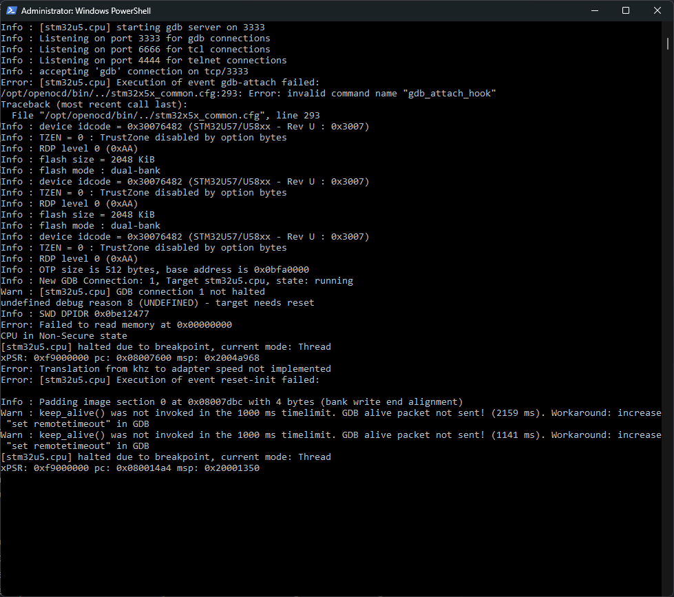
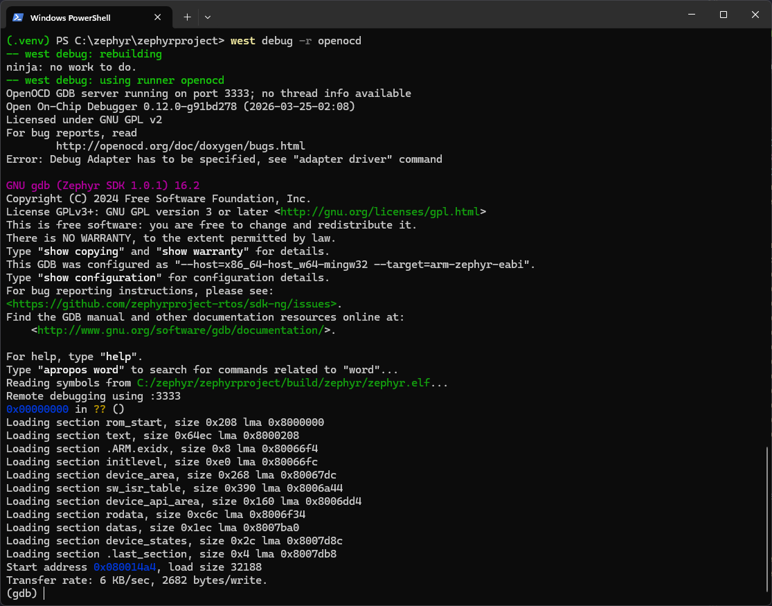
adb forward tcp:3333 tcp:3333 && adb shell arduino-debug, on one line. That is a POSIX shell call, and Windows PowerShell 5.1 has no && operator – you get a parser error. Run them as the two separate commands above, which is clearer anyway given the second one blocks. This is the same class of trap as %HOMEPATH% versus $HOME from my XIAO Thread post: upstream project documentation is usually written for a Linux shell, and the translation to PowerShell is left to you.The west debug call connects GDB to the on-board OpenOCD, loads our image into the STM32's flash, and drops you at a breakpoint on main(): type continue and the comet starts sweeping on the Arduino Uno Q, with the tail fading behind it, and separate green LED flashing.
You have a full source-level debugger into bare-metal firmware, through the Linux computer that shares the PCB, with hardware you owned. (At the time of writing west flash is not yet wired to this on-board adapter, so the debugger doubles as the flasher; an external ST-LINK or J-Link on the SWD pins works with the usual runners if you prefer a standalone flash. Check the board doc in your tree, as this is exactly the kind of gap that closes between releases.)
It will keep running until you type CTRL^C in the gdb terminal:
Program received signal SIGINT, Interrupt.
arch_cpu_idle () at C:/zephyr/zephyrproject/zephyr/arch/arm/core/cortex_m/cpu_idle.c:104
104             __enable_irq();
(gdb) exit
A debugging session is active.
        Inferior 1 [Remote target] will be detached.
Quit anyway? (y or n) y
This will end the comet pattern on the LED matrix.
Video 2. The comet sweeping across the LED matrix
Two consequences of what we just did deserve clarification:
- The Arduino world on the MCU is gone. Our image links at address zero and owns the chip; the sketch loader from Part 1 was overwritten. App Lab's Linux half still runs, but Apps that need the MCU will fail until you restore it.
- Restoring it is one documented command, run from your PC with the board connected (or on the board itself in standalone mode), and it is the same
arduino:zephyr:unoqFQBN from Part 1 doing the work:
(.venv) PS C:\zephyr\zephyrproject> adb shell arduino-cli burn-bootloader -b arduino:zephyr:unoq -P jlink
Open On-Chip Debugger 0.12.0+dev-ge6a2c12f4 (2025-05-22-15:51)
Licensed under GNU GPL v2
For bug reports, read
        http://openocd.org/doc/doxygen/bugs.html
debug_level: 2
clock_config
/tmp/remoteocd/zephyr-arduino_uno_q_stm32u585xx.elf
/tmp/remoteocd/zephyr-arduino_uno_q_stm32u585xx.elf
Info : Linux GPIOD JTAG/SWD bitbang driver (libgpiod v2)
Info : Note: The adapter "linuxgpiod" doesn't support configurable speed
Info : SWD DPIDR 0x0be12477
Info : [stm32u5.ap0] Examination succeed
Info : [stm32u5.cpu] Cortex-M33 r0p4 processor detected
Info : [stm32u5.cpu] target has 8 breakpoints, 4 watchpoints
Info : [stm32u5.cpu] Examination succeed
Info : [stm32u5.ap0] gdb port disabled
Info : [stm32u5.cpu] starting gdb server on 3333
Info : Listening on port 3333 for gdb connections
CPU in Non-Secure state
[stm32u5.cpu] halted due to debug-request, current mode: Thread
xPSR: 0x41000000 pc: 0x080053c2 psp: 0x20000f30
Info : device idcode = 0x30076482 (STM32U57/U58xx - Rev U : 0x3007)
Info : TZEN = 0 : TrustZone disabled by option bytes
Info : RDP level 0 (0xAA)
Info : flash size = 2048 KiB
Info : flash mode : dual-bank
Info : Padding image section 2 at 0x080374f4 with 12 bytes (bank write end alignment)
Error: verify failed in bank at 0x08000000 starting at 0x00000000
Info : Padding image section 2 at 0x080374f4 with 12 bytes (bank write end alignment)
Warn : Adding extra erase range, 0x08037500 .. 0x08037fff
shutdown command invoked
(.venv) PS C:\zephyr\zephyrproject>
-P jlink, on a board whose adapter is CMSIS-DAP. The upstream board documentation specifies this setting. -P names the programmer entry that arduino-cli looks up in its own configuration, and the entry happens to be labelled jlink regardless of what the underlying adapter really is. A useful reminder that a tool's vocabulary is whatever its author chose, not a description of your hardware.That reversibility is what makes this part safe to actually do, rather than merely read: round-trip it once (Zephyr on, play, loader back, App Lab works again) and the board's whole software stack stops being a black box.
Error requesting gpio line swdio means your debug server is still running. Run the restore while the previous section's debug session is still alive and it fails like this, which reads alarmingly like a broken board: Failed to burn bootloader: uploading error... The QRB2210 has no hardware SWD peripheral: its OpenOCD bit-bangs SWD over ordinary GPIO lines through Linux's libgpiod, and libgpiod hands a line to exactly one consumer at a time. So while adb shell arduino-debug is still attached in your other terminal, it owns swdio, and the second OpenOCD that burn-bootloader starts cannot have it. Press Ctrl-C on the arduino-debug terminal, then confirm the remote process actually died using: adb shell pgrep -a openocd followed by: adb shell pkill -f openocd if anything was displayed. Finally, tidy the port mapping using: adb shell pgrep -a openocdWatching the console
One habit from the XIAO series needs adjusting. There, printk arrived over a USB serial port on your PC, and you read it in PuTTY. Here, nothing appears anywhere obvious, and finding out why was a short journey that teaches more about this board than the answer itself does. Our firmware certainly is printing. prj.conf never asked for a console, but the board's own arduino_uno_q_defconfig does the asking for us:
CONFIG_SERIAL=y
CONFIG_CONSOLE=y
CONFIG_UART_CONSOLE=y
which is the same "the board port carries the complexity" pattern as the LED matrix. Confirm it in your own build with grep CONFIG_PRINTK build/zephyr/.config. So bytes are leaving the STM32 at 115200. The question is where they go.
The instinct, given a board with Linux on it, is to SSH in and hunt through /dev. Do that and you will find /dev/ttyMSM0, try it, and get nothing. It is a red herring, and one command explains why:
arduino@DerekQ:~$ cat /proc/consoles
ttyMSM0              -W- (EC  p  )  238:0
tty0                 -WU (E   p  )    4:7
The C flag marks the preferred kernel console. /dev/ttyMSM0 is the QRB2210 talking to itself; it has nothing to do with the STM32. Meanwhile the UART that genuinely does bridge the two chips is already taken, and the process list says so plainly:
arduino@DerekQ:~$ ps aux | grep arduino-router
root  628  /usr/bin/arduino-router --unix-port /var/run/arduino-router.sock
      --serial-port /dev/ttyHS1 --serial-baudrate 115200 ...
/dev/ttyHS1 is the Bridge, and it pairs with lpuart1 – the flow-controlled UART on port G from the board tour. Which leaves usart1, our console, and the connector file already told us where that goes: D0 and D1 on the Arduino header.
Serial. Nothing on the Linux side is listening to it. That is a considerate piece of design rather than an oversight, and it means the way to read your console is the way you would read any Arduino's.The reliable way: a serial adapter on the header
Any 3.3 V USB-to-serial adapter will do. You only need to listen, so two wires:
Leave the adapter's TX and its power pin disconnected. Then open the adapter's COM port at 115200 8N1 from your PC, in PuTTY or whatever you used in the XIAO series, and the die-temperature line appears once a second:
*** Booting Zephyr OS build v4.4.99 ***
=== vanilla Zephyr on the UNO Q (STM32U585) ===
die temperature: 34.21 degC
die temperature: 34.28 degC
What you gained, what you gave up
The Bridge row is the important cost. Parts 1 and 2 got MPU-MCU RPC for free; at this level the internal UART is just a UART, and structured communication is yours to design (the XIAO series' HTTP-over-Thread and CoAP posts are, not coincidentally, studies in exactly that kind of design).
Conclusion
- The UNO Q's MCU is a first-class mainline Zephyr target:
west build -b arduino_uno_qin the same workspace as every Zephyr project from my XIAO series, no vendor fork, no porting. - The 13×8 matrix is the deepest lesson: charlieplexing in the devicetree, a timer-ISR scan in the driver, a standard display device to your code, and a grayscale capability the higher layers never exposed. Abstractions are choices, and going below them is how you find what was omitted.
- The MPU-as-debug-adapter flow (
adb+ on-board OpenOCD +west debug) removes the last hardware barrier between using this board and doing serious bare-metal work on it. burn-bootloadermakes this descent reversible, which means the bare metal work is safe.
This is the deepest point the series reaches so far. Going down the stack was how we found out what the board actually is, and what the layers above had been choosing on our behalf. From here the series climbs back up the software stack, because the next projects worth building on the UNO Q live where the two brains cooperate rather than at either extreme, and they are much easier to design once you know what is underneath them.
What you take with you is that the middle is just layers, and you have now seen through every one: App Lab, the Arduino core, the sketch loader, and the RTOS beneath them all. The XIAO series' argument that Zephyr has become the common tongue of modern embedded work gets its confirmation here from an unexpected and very interesting development board.

