New Version for newer versions of Linux (3.8.x)
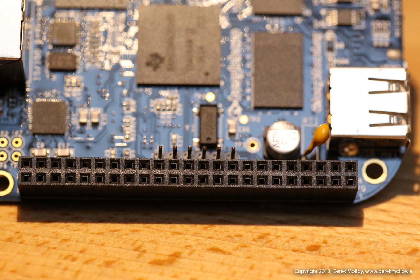
In this video I am going to continue my series on the Beaglebone by demonstrating how to use its GPIOs for both input and output applications. In this video I will wire simple input and output circuits that are attached to two GPIOs – one that lights an LED and the other that receives a button input. I covered this topic below before in a previous video. I am updating it here because there have been significant changes to the Linux kernel. This video will cover the Linux device tree for ARM embedded systems and explain how you can create custom device tree overlays to configure the GPIOs for your applications at run time from within the Linux userspace. I will explain the use of internal and external pullup and pulldown resistors and I will make available and describe a set of C++ code examples for reading and writing to the Beaglebone’s GPIOs. I have also built a set of PDF tables that aggregate the information that you need and make it easier to configure GPIOs on your Beaglebone’s P8 and P9 headers.
The code for the new version of this video is available using:
1 | git clone git://github.com/derekmolloy/boneDeviceTree/ |
The two PDF documents listed in this video are available below (P8 and P9 Headers):
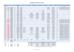
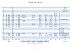
Press on the image and then press “view raw” to view the PDF files. These are available in the docs directory of the github repository above.
There is more information in this content available in my blog post at: http://derekmolloy.ie/gpios-on-the-beaglebone-black-using-device-tree-overlays/
Old Version for older versions of Linux (<3.8)
In this video I extend my series on introducing the Beaglebone and developing applications using embedded Linux to demonstrate how we can build an application that uses its GPIOs (General Purpose Input/Outputs). The example demonstrates a simple LED output circuit and a simple pushbutton input circuit that we can connect to the Beaglebone GPIOs directly. I then go through the steps on how we can configure and access these GPIOs using Sysfs in embedded linux and then demonstrate how we can write a C/C++ program that works directly with these pins. Finally I demonstrate how we can use polling to wait for a GPIO input such as a button press or key press. This application is relevant to all flavours of embedded Linux.
The code that the final application is based on is available at: https://www.ridgerun.com/developer/wiki/index.php/Gpio-int-test.c
The source code in this video is available through githhub:
1 | git clone git://github.com/derekmolloy/beaglebone |
The 4,500 page document that I mention 15 minutes in is available for download from Texas Instruments’ Website. It is called “AM335x ARM(r) Cortex(TM)-A8 Microprocessors(MPUs)”. The version I have is “Literature Number: SPRUH73C” from Oct’11(revised Dec’11).
Hi Derek, I have been following your tutorials for gpio devicetree for my BBB. I want to modift the dts file you have and recompile it. When I run the build script, I get the following error:
Compiling the overlay from .dts to .dtbo
Error: DM-GPIO-Test.dts:35.1-3 syntax error
FATAL ERROR: Unable to parse input tree
uname -a give the following
Linux beaglebone 3.8.13 #1 SMP Wed Jun 5 11:21:00 CEST 2013 armv7l GNU/Linux
and dtc -v gives me Version: DTC 1.3.0-g27cdc1b1-dirty
What I am missing? Can you help?
Thanks,
Rajah
hello Derek,
actually I get a similar problem as Rajah up here
uname -a
Linux debian-armhf 3.8.13-bone20 #1 SMP Wed May 29 03:11:01 UTC 2013 armv7l GNU/Linux
dtc -v
Version: DTC 1.3.0
(I’m on wheezy, I installed it with apt-get install, and I see it downloaded the latest 1.3.0-4 version)
launching your build it was complaining on the “-@” parameter… it seems -@ is not correct: it is enough to set the input file at the end of the command line;
so the build becomes:
dtc -O dtb -o DM-GPIO-Test-00A0.dtbo -b 0 DM-GPIO-Test.dts
and I get:
Compiling the overlay from .dts to .dtbo
DTC: dts->dtb on file “DM-GPIO-Test.dts”
Error: DM-GPIO-Test.dts:15.2-8 syntax error
FATAL ERROR: Unable to parse input tree
I see that it complains on this row (I think):
/plugin/;
any hint is more than welcome;
thanks
Giovanni
@Raja & Giovanni:
I had the same problem, but I fixed it! In the DM-GPIO-Test.dts-file you have to comment out the following lines:
/* <<<<<<>>>>>> f83cf685371044f2fbc8e8da09759bed24038367 */
That helped for me!
Best regards,
Christoph
:-\
I already had removed those lines! so, I still have the problem…
what is quite strange is that dtc version used by Derek accepts the
-@
for defining the input file,
and dtc installed with apt-get install from wheezy does not…. (b.t.w. it is the most recent version).
it seems that on Angstrom there is a different version of dtc with respect to wheezy
Giovanni
Hi Giovanni,
It is my understanding that if you want to use dtc to enable/disable the GPIOs or I2C, SPI etc. without needing to recompile the bootloader device tree then you need the @ option in dtc, which comes via a patch. Thankfully this came pre-patched and pre-built with the Angstrom distribution for the Beaglebone but the alternative is to download the source code for dtc and manually patch and compile it.
Kind regards,
Derek.
Good day! I simply want to give an enmuoors thumbs up for the good data you could have right here on this post. I might be coming again to your blog for extra soon.
Derek,
I wish I’d found your video 10 days ago! I’ve looked over the SRM and TRM and just got overwhelmed. I’ve read and re-read BBB forums and blogs. You put together the issues that had me in a daze: modes, pin addressing and numbers, claimed and available pins, setting pullup/downs and how to access the gpio from a c/c++ program. The device tree overlay was explained well enough for me to play with them, but there’s still black magic in them. What is up with the naming conventions? i.e. fragment? and “00A0″. Do you have a reference for using gpio interrupts? There were other items in the gpio directory. In particular, “edge” and “uevent”. What are these?
I don’t care if you can answer these question or not. What you’ve done has explained in 45 minutes what I couldn’t get clear in 10 days, I am a bit slow, I gotta admit that, but that shouldn’t take away from the great jobs you’ve done.
Thanks,
Ron
Hello Derek,
thanks for the genious description, which helped me a lot getting my former Linux 3.3 based project ported to Linux 3.8. It worked on the very first try.
Günter
http://radarcape.bplaced.net/wiki/doku.php
http://www.modesbeast.com
Hi
This is a way to compile dtc with -@ switch available:
$ git clone git://www.jdl.com/software/dtc.git
$ cd dtc
$ git checkout 27cdc1b16f86f970c3c049795d4e71ad531cca3d
$ wget https://github.com/beagleboard/meta-beagleboard/raw/master/common-bsp/recipes-kernel/dtc/dtc/0001-dtc-Dynamic-symbols-fixup-support.patch
$ patch -p1 < 0001-dtc-Dynamic-symbols-fixup-support.patch
$ make
MK
Thanks Michał – that is very useful! Derek.
Derek, please remove “../” in patch -p1 < ../0001-dtc-Dynamic-symbols-fixup-support.patch :]
Fixed. Thanks.
Im getting a strange error after loading my overlay:
[ 84.017830] bone-capemgr bone_capemgr.9: part_number ‘DM-GPIO-Test’, version ‘N/A’
[ 84.021955] bone-capemgr bone_capemgr.9: slot #7: generic override
[ 84.022021] bone-capemgr bone_capemgr.9: bone: Using override eeprom data at slot 7
[ 84.022075] bone-capemgr bone_capemgr.9: slot #7: ‘Override Board Name,00A0,Override Manuf,DM-GPIO-Test’
[ 84.022371] bone-capemgr bone_capemgr.9: slot #7: Requesting part number/version based ‘DM-GPIO-Test-00A0.dtbo
[ 84.022425] bone-capemgr bone_capemgr.9: slot #7: Requesting firmware ‘DM-GPIO-Test-00A0.dtbo’ for board-name ‘Override Board Name’, version ’00A0′
[ 84.030939] bone-capemgr bone_capemgr.9: slot #7: dtbo ‘DM-GPIO-Test-00A0.dtbo’ loaded; converting to live tree
[ 84.031329] bone-capemgr bone_capemgr.9: slot #7: #2 overlays
[ 84.036694] bone-pinmux-helper helper.11: could not find pctldev for node /ocp/interrupt-controller@48200000, deferring probe
[ 84.036760] bone-pinmux-helper helper.11: Failed to get pinctrl
[ 84.063050] platform helper.11: Driver bone-pinmux-helper requests probe deferral
[ 84.063393] bone-capemgr bone_capemgr.9: slot #7: Applied #2 overlays.
Do you have any idea why the bone-pinmux-helper does not work?
Kernel: Linux arm 3.8.13-bone21
Dist: Ubuntu 13.04
I have the exact same problem running ArchLinux on the beaglebone black.
Does anybody have a solution?
Was a solution ever found for this error? I’m having the same issue.
Any solution to this? I’m having the same issue:
[785508.309670] bone_capemgr bone_capemgr: part_number ‘DM-GPIO-Test’, version ‘N/A’
[785508.309746] bone_capemgr bone_capemgr: slot #5: override
[785508.309787] bone_capemgr bone_capemgr: Using override eeprom data at slot 5
[785508.309832] bone_capemgr bone_capemgr: slot #5: ‘Override Board Name,00A0,Override Manuf,DM-GPIO-Test’
[785508.326306] bone-pinmux-helper ocp:helper: could not find pctldev for node /ocp/interrupt-controller@48200000, deferring probe
[785508.331356] bone_capemgr bone_capemgr: slot #5: dtbo ‘DM-GPIO-Test-00A0.dtbo’ loaded; overlay id #1
Derek,
I’m a consulting Electrical Engineer with 30+ years of experience. I’m starting a project based on the Beaglebone Black.
Love your stuff. I just wanted to say thank you.
Jack
Hi Derek,
thanks a lot for the high quality informations and videos!
Currently I am trying to get the LCD7 (A2) cape and AUDIO (only, no DVI)-cape running
on the Beaglebone black (A5C).
I got them both running with my Beaglebone classic.
But with the Beaglebone Black the LCD7 flashes instantly right after the kernel has started.
I have disabled eMMC and HDMI via uEnv.txt.
Booting the BBB either with LCD7- or with the AUDIO cape works.
I think I have identified the pins which both capes think they are their own… 😉
The question is:
Is it possible to manipulate the GPIO pins from the U-boot / uEnv.txt untill the kernel takes over
the control to avoid any “default settings” killing one or both of my apes?
Thank you very much in advance for any help!
Best regards,
mcc
Hi Derek,
Thanks for your work!
To learn dt overlays better I am trying to disable the “heartbeat” led.
Here is my overlay file:
http://pastebin.com/raw.php?i=50tLtKy3
Note that the only change to the overlay file from the default dts is that I changed line 23 from “heartbeat” to “none”
I can compile and load this overlay ok, but the led doesn’t stop flashing the heartbeat.
Any ideas on why it isn’t working properly?
Thanks.
Ray
Hi Derek,
Thanks for your tutorial!
I’ve got a problem with my white Beaglebone. I can’t set timer5 function on P8_9 pin (gpmc_ben0_cle, mode2 : see Table9 from Bone_SRMRevA6). The timer5 function is not available on this pinmux, all that i see when i’m trying to configure this pin from the omap_mux (kernel) is:
# cat gpmc_ben0_cle
name: gpmc_ben0_cle.gpmc_ben0_cle (0x44e1089c/0x89c = 0x0000), b NA, t NA
mode: OMAP_PIN_OUTPUT | OMAP_MUX_MODE0
signals: gpmc_ben0_cle | NA | NA | NA | NA | NA | NA | gpio2_5
Have you got any idea to help from this issue because I need this function to use an external signal to trigger the TSC_ADC, in my project?
Thanks in advance.
Geoffrey,
Have you sorted the problem out? I have the same problem when trying to use gpme_ben0_cle.gpio2_5 in kernel. I can only turn on/off this pin at user space and no luck at device tree.
How would I go about doing a GPIO device tree overlay for the debian 7.1 image (link below)? I tried with your dts but it fails to load with the error “echo: write error: No such file or directory” when I try to echo it to the slots, Which does exist because I can cat it and get a list of loaded capes.
http://elinux.org/BeagleBoardDebian#Demo_Image
Hi Derek
i have search about C source code about “how to configure LCD 16×2 in BBB” on google.com, but i can’t find Source code. do you have sample C Source code about my problem??
if you have, please send to my email : a4n_impulse@yahoo.co.id
Sorry for my bad English
Just using your tables
Could you confirm on P8 PDF Header.pdf at the bottom that the 2nd-4th LEDs are on GPIO2 and not GPIO1?
Also the text P9 Header below P8_46 is that correct?
Hi Derek,
thank you a lot for this video, it made the practical usage of the GPIO module a lot clearer.
Have you already experimented with interrupts on the GPIO-ports? If so, could you provide any practical example how to configure them? Since polling for changes on pins is very CPU-stressing, I guess it would be very helpful to lots of programmers.
Thank you again and best regards,
Martin
Hi,
I have some questions. I check GPIO1_0 for my RS485 cape, you mark it GPIO No to 1. But should it be 32 since 32*1 + 0 = 32….
Also if I wanna just use GPIO1_0 and GPIO1_4 to output “1” or “0”, Do I nessescary need to change the device tree file(dts file), could I just export it using your c code?
Sorry for my english
Yiqing
Hi Yiqing, Thanks for that – I will fix GPIO1_0 in the sheet. You will have to use the dts code if they are not in the right mode. Derek.
Hi Derek,
Hi Derek,
The stuffs by you are going great!!!. I just want to know how to interface a 16*2 LCD with BBB via GPIOs. I have been trying different things. But cud not do so.If possible , help me out in this issue.
Hello Derek,
I am following your tutorials and I really appreciate that you put all this together! It helps a lot and helped me a lot!
I am currently looking for switching my BB into sleep mode, namely “suspend”. I build an ubuntu (3.2) kernel with Power Management support from the standard sources available and enabled the required features in the kernel config (no source modifications done). With this I am able now to put the BB into sleep mode via “echo mem > /sys/power/state”. Now I want to wake it up again … This is where GPIO comes into the game. According to what I found so far only GPIO_0 (bank 0) supports wake-up. So I added (for test) a switch to GPIO0_7 (as I did before at other pins) and made sure that prior to “suspend” the pin is configured to be an input (I tested it to make sure the the button input works). However, when I put the BB to sleep neither edge/state wakes it up again. Do you have any idea what needs to be configured in addition to the mode/direction etc so that a GPIO0_x pin wakes up the BB?
Thanks a lot in advance! I appreciate your feedback!
Regards,
Thomas
Hallo Thomas,
Did you find any lead on this? I need to configure my DCAN as wake up source but kind of stuck on how to achieve that.
Kind regards,
Niranjana
Wow Derek,
At last I begin to understand. These device tree things could be great.
I think I’ve got the offset and mode thing worked out. Not that different from the pin muxing I’ve struggled with on other devices.
I’m trying to get 18B20 sensors working with the BBB. There are a couple of posts around describing things, but I’m not understanding what I am seeing.
The device trees I see for the subject each have another fragment, something like:
fragment@1 {
target = ;
__overlay__ {
onewire@0 {
compatible = “w1-gpio”;
pinctrl-names = “default”;
pinctrl-0 = ;
status = “okay”;
gpios = ;
};
Now, I think I get some of this fragment. I completely loose it when it comes to this line…
gpios = ;
is this yet another way to specify a pin?
Your help is much appreciated.
Matt
Try the formating again, sorry
“fragment@1 {
target = ;
__overlay__ {
onewire@0 {
compatible = “w1-gpio”;
pinctrl-names = “default”;
pinctrl-0 = ;
status = “okay”;
gpios = ;
};
”
Now, I think I get some of this fragment. I completely loose it when it comes to this line…
“gpios = ;”
is this yet another way to specify a pin?
Your help is much appreciated.
Matt
how to interface Touch screen lcd display with Beaglebone black?
Hi Derek! Tks for the video and informations!
But I use kernel 3.12 and target = just doesn’t exist.
All foruns I looked for an answer says “downgrade kernel…”
Is there any other option?
Best regards!
I mean, target = ocp
I wrote the full ine but the tags were removed from the post.
When trying to echo to SLOTS, dmesg says “could not find symbol ‘ocp’.
Tks
Hi Derek! I’m a guy who lives in China.
For some political reasons I (and other people) can’t visit youtube!
Could you send me a copy of videos?
Thanks a lot!
Best Regards.
Hans
Hi Derek!
First of all I want to thank you for this great compilation of useful information. I’ve searched quite a while to get all required information’s together, just to find out everything I needed is here in one place 😉
Is it possible to get the base data for the Header PDF’s you provided via git? These are by far the most comprehensive I’ve seen so far, but they are missing the PRU mapping (pr1_pru[0|1]_*), as I’m currently using the PRU quite heavily I just wanted to add them and share the updated versions with you.
Frank
Derek,
I’ve watched several of your on-line blogs / videos and find them to be some of the most efficient blogs I’ve ever found on any topic. Most videos I find elsewhere are either painfully slow to develop or gloss over important details. Yours don’t miss a thing yet move at a nice pace. I’m a first timer on most topics so I’ll admit that it takes me about three hours to get through some of your content because I end up pausing & re-winding as I test and verify behavior
If I had an observation (and it is a VERY minor one) it is that on the youtube video the command line you are typing on is often partially covered up by the youtube controls that pop up when you pause/play the video… cropping the video such that there was an extra 1/2 inch at the bottom would allow the youtube controls to appear without graying out the command line. This probably isn’t a problem for most people that are more familiar with SSH and commands but for a first timer like me it is a little harder to keep pace since I am looking closely at your commands to get syntax and such. I provide this comment in the most positive way possible and hope you won’t take it in a negative way as I will gladly work through this on any topic you post.
Again, THANK YOU! Your videos have made the $45US I spent on my BBB the most enjoyable use of money in a long time.
Lance
Thanks Lance,
That is very useful to know,
Derek.
A reference !
Thanks a lot !
To save someone else from tearing out his or her hair: note that the name of the file DM-GPIO-Test is only 12 characters long. If you make a similar file but extend its name beyond 16 characters, the step
echo Extended-File-Name > $SLOTS
will fail with the misleading message that the file doesn’t exist. Since the only file in the command is $SLOTS, which clearly does exist, the message makes no sense.
Reduce the file name to 16 characters or fewer, and it will work as it should. It appears that the file name and the internal labels must agree (but I’ve not tested this), so make any adjustments necessary in the .dts file.
[Debian, with the 3.8.13 kernel]
Thanks Richard, Derek.
Derek,
First off, thanks for all the good information you provide on your site!
So my issue is, I cannot get P9_25 to work as an “in” at all…
I have disabled the HDMI audio oscillator (so I think), see below.
# cat /sys/devices/bone_capemgr.*/slots
0: 54:PF—
1: 55:PF—
2: 56:PF—
3: 57:PF—
4: ff:P-O– Bone-LT-eMMC-2G,00A0,Texas Instrument,BB-BONE-EMMC-2G
5: ff:P-O– Bone-Black-HDMI,00A0,Texas Instrument,BB-BONELT-HDMI
6: ff:P-O– Bone-Black-HDMIN,00A0,Texas Instrument,BB-BONELT-HDMIN
7: ff:P-O-L Override Board Name,00A0,Override Manuf,DM-GPIO-Test
But, whenever I try to export P9_25, I get the following…
# dmesg (subset)
[ 6824.011254] gpio_request: gpio-117 (sysfs) status -16
[ 6824.011276] export_store: status -16
The pin gets set to “in”, but is always high
# cat /sys/kernel/debug/gpio
GPIOs 0-31, gpio:
gpio-6 (mmc_cd ) in lo
GPIOs 32-63, gpio:
gpio-53 (beaglebone:green:usr) out lo
gpio-54 (beaglebone:green:usr) out lo
gpio-55 (beaglebone:green:usr) out hi
gpio-56 (beaglebone:green:usr) out lo
GPIOs 64-95, gpio:
GPIOs 96-127, gpio:
gpio-117 (sysfs ) in hi
Hi, I think that File I/O would be very slow compared to memory writing.
Are not these I/O pins memory mapped ?
Or under the hood, these file writing are talking to memory indirectly, which means inefficient for us.
Can not we read/write directly in memory ?
It depends. Yes it is limited in switching speed, but if you just want to enable a pin to be high/low then it is fine. It is called sysfs and it is a memory mapping to something that looks like a file system. So, it is memory mapped and reasonably quick. The alternative is to write a device driver/loadable module that you deploy into kernel space – Not easy!
Derek, not true at all! Direct memory writes, using something like mmap, give around 4MHz toggle speeds, where sysfs is a few hundred kHz.
Mmap does not require a kernel driver and can be done even in python: http://www.alexanderhiam.com/tutorials/beaglebone-io-using-python-mmap/
And, since there’s a set and clear gpio register for each bank, read-write-modify isn’t required.
Also, you get the benefit of being able to simultaneously set gpio.
See http://www.alexanderhiam.com/tutorials/beaglebone-io-using-python-mmap/ for a Python example. If your language supports mmap, the process is the same.
You can set output states, clear output states, read pin states, and enable and disable the output driver (to set to input/output) through memory.
Muxing the pin and things like pull-ups do require kernel level access like device tree. For easy pin muxing with some pre-defined device tree overlays, see: https://github.com/nomel/beaglebone/tree/master/gpio-header
Hi Derek,
Thanks a lot for the info provided about the device tree overlay and gpio’s. I recognized that a lot of the “free” (free for use) pins are in mode 0x0037 by default. Meaning that these pins are already high after boot (3V3 applied to board pin). I can change this with the device tree overlay. However, for a short time (until the overly was applied) the connected electronics receive the default high (3V3). I would like that the “free” pins directly boot into 0x000F mode (mode 7 and PullUp/PullDown disabled). Later I can use device tree overlay to set the pins according to the needs and connected electronics. Do you know how to do this? Do I need to change the .dtb’s located in /boot and if so how?
Many thanks for your help and answer. Best regards, Nico
Hello Dr. Molloy,
I took several days trying to understand device tree overlays, and your video was key to helping me understand them (that and the links to original device trees of the AM335x and Beaglebone).
I put one together, but perversely, I tried to play with the GPIO lines without sending the overlay to $SLOTS. To my surprise, it worked. Which raises a bigger question for me. While I understand the need to use overlays to expose/access the peripherals of the Beaglebone Black, I don’t quite understand why it’s necessary for GPIO, aside from perhaps ensuring a pull-up is enabled on inputs.
The device tree overlay is doing two separate things in htis case. One is that it sets the pin mux registers so the signals to/from the physical pin are connected to the proper internal signals in the chip (gpio in this case). The other, with the gpio-helper stuff, is that it loads sysfs interfaces for gpio.
You’re absolutely correct. You can just use the device tree to mux the pin, and then use memory writes to modify the gpio. The sysfs interface is entirely optional. BUT, the benefit of the sysfs interface is that porting your code will be easier if you ever move to a different platform. With memory reads/writes, you’re *always* limited to a specific piece of hardware. But, the closer you get to the hardware, the better performance you can squeeze out. In the sysfs case, gpio toggle speeds are limited to a few hundred kHz, where memory writes are around 4MHz! The sysfs gpio interfaces were not meant with performance in mind since each operation requires completely opening and closing a file handle (insane) rather than, say, streaming in bytes.
Hello Derek,
Thanks for sharing all this info, it is helping me a lot.
I do have a problem and that is I can get the SimpleGPIO to compile om my desktop-pc, I have a lap-top and there everything is ok. The only difference I can find is that there is a directory /sys/class/gpio om my lap-yp and it’s not on my desk-top and I can not copie it..
can you give me any sugestions?
regards
Arie
Hi Derek,
Did a compleet re-install and seems to be working ok now..
Am running Ubuntu 13.10..
Hi.
Thanks for the such a nice video tutorials on BBB. Here i am trying to change the GPIO pin mode to MODE 7 i.e.Digital I/O….i follow the same procedure given in video , and i edit the DM-GPIO-Test.dts file as follows by adding pin offset nd set them…nd after compiling this file successfully . and after completing…i check the GPIO pin mode but its not gets changed. It remains default. …here are the changes i made in the DM-GPIO-Test.dts file as follows…..i am new to “devicetree” , if i have made any mistake so plz tell me….
/*
* Copyright (C) 2012 Texas Instruments Incorporated – http://www.ti.com/
*
* This program is free software; you can redistribute it and/or modify
* it under the terms of the GNU General Purpose License Version 2 as
* published by the Free Software Foundation
*
* Original from: github.com/jadonk/validation-scripts/blob/master/test-capemgr/
*
* Modified by Derek Molloy for the example on http://www.derekmolloy.ie
* that maps GPIO pins for the example
*/
/dts-v1/;
/plugin/;
/{
compatible = “ti,beaglebone”, “ti,beaglebone-black”;
part-number = “DM-GPIO-Test”;
version = “00A0”;
fragment@0 {
target = ;
__overlay__ {
pinctrl_test: DM_GPIO_Test_Pins {
pinctrl-single,pins = ;
};
};
};
fragment@1 {
target = ;
__overlay__ {
test_helper: helper {
compatible = “bone-pinmux-helper”;
pinctrl-names = “default”;
pinctrl-0 = ;
status = “okay”;
};
};
};
};
Hi Derek,
I’m tryting to toggle an output GPIO bit from a kernel driver (for critical timing) – I was able to do this on the original BeagleBone board by first setting up the appropriate ‘region’
request_mem_region(AM33XX_CONTROL_PADCONF_MUX_PBASE, 0x1000, DEVICE);
control_module_start = ioremap (AM33XX_CONTROL_PADCONF_MUX_PBASE, 0x1000);
and then the specific port …
__raw_writel (OMAP_MUX_MODE7, control_module_start+AM33XX_CONTROL_PADCONF_GPMC_AD6_OFFSET));
…. and gpio_direction_output() to change the output pin state ..
I mapped AM33XX_CONTROL_PADCONF_MUX_PBASE to 0x44e10800 and ..GPMC_AD6_OFFSET to 0x18.
Should this method still work with the Device Tree now in place? Any other Device Tree setup required?
thanks, Rich F
Hi, your videos are very instructive. I noted the pdf files with pin tables for P8 and P9. I would like to convert these to text for inclusion in Python, etc. programs, but there doesn’t seem to be a way to extract such tables from a pdf file.
Can you send me these tables in spreadsheet or csv format? It would save a lot of time over poring over the screen images of the tables. The beagle.org and ti docs are also in pdf format, so I can’t use those.
I wrote dts for eQEP0 and compiled it by dtc on “Linux beaglebone 3.8.13 #1 SMP Wed Sep 4 09:09:32 CEST 2013 armv7l GNU/Linux” then met error : “Error: bone_eqep0.dts:24.8-15 syntax error
FATAL ERROR: Unable to parse input tree”, I tried to review but did not found error, can you please help me deal with ?
—————————————————
/dts-v1/;
/plugin/;
/ {
compatible = “ti,beaglebone-black”;
/* identification */
part-number = “bone_eqep0”;
version = “00A0”;
/*state the resource in this cape uses *
exclusive-use =
/* the pin header uses */
“P9.27”, /*eQEP0B_in*/
“P9.42”, /*eQEP0A_in*/
“P9.25”, /*eQEP0_strobe*/
“P9.41”, /*eQEP0_index*/
/* the hardware IP uses */
“eQEP0”;
fragment@0 {
target = ;
__overlay__ {
pinctrl_eqep0: pinctrl_eqep0_pins {
pinctrl-single,pins = ;
};
};
};
fragment@1 {
target = ;
__overlay__ {
status = “okay”;
};
};
fragment@2 {
target = ;
__overlay__ {
pinctrl-names = “default”;
pinctrl-0 = ;
count_mode = ; /* 0 – Quadrature mode, normal 90 phase offset cha & chb. 1 – Direction mode. cha input = clock, chb input = direction */
swap_inputs = ; /* Are channel A and channel B swapped? (0 – no, 1 – yes) */
invert_qa = ; /* Should we invert the channel A input? */
invert_qb = ; /* Should we invert the channel B input? I invert these because my encoder outputs drive transistors that pull down the pins */
invert_qi = ; /* Should we invert the index input? */
invert_qs = ; /* Should we invert the strobe input? */
status = “okay”;
};
};
};
———————————-
Need to use 40 IO pins (How can I use the “RED” pins)
Hello Derek,
I really appreciate the work you have put into making these tutorials – simple amazing.
I was going through the tutorial on the Device Tree and you mentioned that if I wanted to use the LCD/HDMI pins (or rather any of the “red” marked pins) as GPIO’s then I should proceed with caution and do some prior reading. Could you suggest a source that I can use to read up. I need to use those pins (I am assuming) because I need almost 40 IO’s in my application.
Regards
Hi Swapnesh,
To disable the HDMI interface, uncomment the line in the uEnv.txt file on the Debian image. Be careful not to uncomment the line that relates to eMMC if you do not wish to only boot from an SD card. Once the devices associated with the red pins are disabled, they are free to be used.
Kind regards,
Derek.
I am using Angstrom v2012.12 – Kernel 3.8.13
shows me the following mesange when you upgrade.
[ 618.998468] bone-capemgr bone_capemgr.7: failed to load firmware ‘BB-BONE-TESTER-00A0.dtbo’
[ 622.076137] bone-capemgr bone_capemgr.7: failed to load firmware ‘BB-BONE-TESTER-00A0.dtbo’
[ 626.256175] bone-capemgr bone_capemgr.7: failed to load firmware ‘BB-BONE-TESTER-00A0.dtbo’
[ 629.336606] bone-capemgr bone_capemgr.7: failed to load firmware ‘BB-BONE-TESTER-00A0.dtbo’
[ 632.418848] bone-capemgr bone_capemgr.7: failed to load firmware ‘BB-BONE-TESTER-00A0.dtbo’
[ 635.502594] bone-capemgr bone_capemgr.7: failed to load firmware ‘BB-BONE-TESTER-00A0.dtbo’
[ 638.581975] bone-capemgr bone_capemgr.7: failed to load firmware ‘BB-BONE-TESTER-00A0.dtbo’
[ 641.666097] bone-capemgr bone_capemgr.7: failed to load firmware ‘BB-BONE-TESTER-00A0.dtbo’
[ 644.746048] bone-capemgr bone_capemgr.7: failed to load firmware ‘BB-BONE-TESTER-00A0.dtbo’
[ 647.827306] bone-capemgr bone_capemgr.7: failed to load firmware ‘BB-BONE-TESTER-00A0.dtbo’
[ 650.910094] bone-capemgr bone_capemgr.7: failed to load firmware ‘BB-BONE-TESTER-00A0.dtbo’
[ 653.992523] bone-capemgr bone_capemgr.7: failed to load firmware ‘BB-BONE-TESTER-00A0.dtbo’
[ 657.074832] bone-capemgr bone_capemgr.7: failed to load firmware ‘BB-BONE-TESTER-00A0.dtbo’
[ 660.157312] bone-capemgr bone_capemgr.7: failed to load firmware ‘BB-BONE-TESTER-00A0.dtbo’
[ 663.238229] bone-capemgr bone_capemgr.7: failed to load firmware ‘BB-BONE-TESTER-00A0.dtbo’
[ 666.320259] bone-capemgr bone_capemgr.7: failed to load firmware ‘BB-BONE-TESTER-00A0.dtbo’
[ 669.402540] bone-capemgr bone_capemgr.7: failed to load firmware ‘BB-BONE-TESTER-00A0.dtbo’
[ 672.483325] bone-capemgr bone_capemgr.7: failed to load firmware ‘BB-BONE-TESTER-00A0.dtbo’
[ 675.565021] bone-capemgr bone_capemgr.7: failed to load firmware ‘BB-BONE-TESTER-00A0.dtbo’
[ 678.648393] bone-capemgr bone_capemgr.7: failed to load firmware ‘BB-BONE-TESTER-00A0.dtbo’
[ 681.735811] bone-capemgr bone_capemgr.7: failed to load firmware ‘BB-BONE-TESTER-00A0.dtbo’
[ 684.817261] bone-capemgr bone_capemgr.7: failed to load firmware ‘BB-BONE-TESTER-00A0.dtbo’
[ 687.898385] bone-capemgr bone_capemgr.7: failed to load firmware ‘BB-BONE-TESTER-00A0.dtbo’
[ 690.982546] bone-capemgr bone_capemgr.7: failed to load firmware ‘BB-BONE-TESTER-00A0.dtbo’
[ 694.066788] bone-capemgr bone_capemgr.7: failed to load firmware ‘BB-BONE-TESTER-00A0.dtbo’
[ 697.145634] bone-capemgr bone_capemgr.7: failed to load firmware ‘BB-BONE-TESTER-00A0.dtbo’
[ 700.231835] bone-capemgr bone_capemgr.7: failed to load firmware ‘BB-BONE-TESTER-00A0.dtbo’
[ 703.312469] bone-capemgr bone_capemgr.7: failed to load firmware ‘BB-BONE-TESTER-00A0.dtbo’
[ 706.395972] bone-capemgr bone_capemgr.7: failed to load firmware ‘BB-BONE-TESTER-00A0.dtbo’
[ 709.480608] bone-capemgr bone_capemgr.7: failed to load firmware ‘BB-BONE-TESTER-00A0.dtbo’
[ 712.560497] bone-capemgr bone_capemgr.7: failed to load firmware ‘BB-BONE-TESTER-00A0.dtbo’
[ 715.641716] bone-capemgr bone_capemgr.7: failed to load firmware ‘BB-BONE-TESTER-00A0.dtbo’
[ 718.726705] bone-capemgr bone_capemgr.7: failed to load firmware ‘BB-BONE-TESTER-00A0.dtbo’
[ 721.808638] bone-capemgr bone_capemgr.7: failed to load firmware ‘BB-BONE-TESTER-00A0.dtbo’
can you help me please
Hi Derek,
Thanks a lot for throwing light on how to write device tree for BBB….I have been facing timing issues while accessing GPIO pins from Arm processor….I was using 8 pins of P8 header to both read & write data from BBB….This was costing me a time overhead of around 1 usec for each high/low transition of a single gpio pin….Hence I used the PRU sub processor and it helped me to reduce the time taken to nanosecond range….
But my problem is since the PRU uses R30 and R31 register as output and input respectively..I am unable to use the same pins for in/out….I have taken the 8 pins to act as output in dts…
Will you please suggest a method by which I can change the gpio in/out setting on the run inside my program, as i did the same in arm using “gpio_direction_output” & “gpio_direction_input” statements while coding kernel driver…..
Expecting a reply ….
Thanks a lot in advance…..
Parvathy
I only wish I had come across your posts earlier. Really great job explaining the basics and thanks for improving the documentation available.
I am trying to find out if the BBB meets the requirements for my application, where I would need to synchronize and control the delays among 8 IO’s. Would that be possible with the BBB? What would be the shortest time (controlled) between two channels? and the jitter? I have also read about PRU’s, would that be an option to obtain delays in the range of a few ns? Thanks!
Is there a way that i can get those two PDF files mentioned at the top of this page as Word (i..e .doc) files? I’d like to edit out a few columns that I don’t need, and add a couple that I do…
I have no intention of publishing them, the files would be for personal project use only…
Thanks in advance..
Mike
Hi Derek,
I have been actively following your posts and have learnt a lot. I was actually trying to use the TiWi-BLE cape with my BB white but i just could not get it running. It does not respond in any way. I followed the wiki tutorial by circuitco but it did not help. I was wondering if you had any tips. I am using ubuntu linux in my beaglebone.
Thanks in anticipation.
Kishen_bb
Hello, would it be possible to write a tutorial about how to use the analog input of the beagle bone black in C/C++ ?
thanks
ssinfod
More hair pulling – and a question:
I have been trying to write my own .dts file but the pin modes were just not changing as a number of people have reported above.
I then tried to reduce the problem to its simplest and all I did was:
1) echo -7 > $SLOTS
2) Changed a mode in the original DM-GPIO-Test.dts file:
0x184 0x2f /* P9_24 15 INPUT MODE7 none – The Button Input */
was changed to:
0x184 0x07 /* P9_24 15 INPUT MODE7 none – The Button Input */
3) dtc -O dtb -o DM-GPIO-Test-00A0.dtbo -b 0 -@ DM-GPIO-Test.dts
4) echo DM-GPIO-Test > $SLOTS
THEN
cat $PINS|grep ‘984’ # reported
pin 97 (44e10984) 0000002f pinctrl-single
Thus, the mode HAD NOT CHANGED.
But in desperation, if I rebooted the BBB, then followed the same procedure, the Mode of pin 97 correctly changed to 0x07!
I can live with this – but would like to know why the .dbo’s are not correctly updating the pins without a reboot.
Additional pin function for P8.43
Hello Derek,
I like your pinning tables very much, thanks.
I have one thing that might be interesting for others.
The boot switch is connected to P8.43 via a 100Ohm resistor.
This can be usefull if someone puts the bbb into a box but
wants to update it with a eMMC-flasher image.
Than one does not have to unbox the bbb.
Regards Martin
Thanks Martin, Derek.
Derek: “permission denied” is actually preventing me from getting GPIO going on my Rev C (debian) BBB. Basically the “echo N > sys/class/gpio/export” only works with root access, and so any C++ program that attempts to write to that pseudo-file is going to get blocked. Do you know of a straightforward way, without having to write a GPIO driver thus making the sysfs implementation meaningless, to get C++ code to talk to GPIO?
Note: I have explored the setuid() option. It’s not ideal, particularly because I use Netbeans with remote development on my PC to write my code, and it ignores the setuid bit when running or debugging.
Hi Julain, I feel bad about saying this, but I have a solution to this at the end of Chapter 6 of my book “Using GPIOs without Using sudo”. The trick is to udev rules… You can find my udev rules file at: https://github.com/derekmolloy/exploringBB/tree/master/chp06/udev
Derek.
Hi Derek,
Have you done anything using 2 GPIO pins for 2 onewire lines. I’ve got a string of 10 DS1820s running on 1 port but can’t seem to get an overlay to work to drive 2 separate lines. Eventually I want to get 40 sensors running but 1 step at a time
Great blogs by the way.
Cheers
Dave
Hi Derek,
Thanks for posting such useful content on your site – it has been quite a help!
I’m using Angstrom v2014-06 (Linux 3.8.13 kernel) on Beaglebone RevA6b (not Beaglebone Black), and am using a custom DT overlay to configure pin mux for my application. I need to set gpio1_2 to be an output (mux mode 0x1F – RXACT disabled/Output, Pullup (disabled), mode 7).
The overlay appears to load OK, with no errors in dmesg output, and the overlay slot appears when I cat /sys/devices/bone_capemgr.*/slots.
The pin mux assigments and modes appear to be correct in /sys/kernel/debug/pinctrl/44e10800.pinmux/pins and in /sys/kernel/debug/pinctrl/44e10800.pinmux/pingroups.
The pins export properly and appear in /sys/class/gpio.
When I manipulate the pins by writing 1 or 0 to output pins in /sys/class/gpio/gpioN/value, most of them change level (measured with a logic analyzer or voltmeter).
One of the pins, however, gpio1_2 (aka P8_5 or gpio34), does not change when writing to /sys/class/gpio/gpio34/value.
Oddly, /sys/class/gpio/gpio34/direction indicates that it is an output, and /sys/class/gpio/gpio34/value changes when I write to it, but the pin voltage never changes. I am testing the pin on a bare board – no external hardware is present. I’ve tested this on multiple beaglebone boards, so not likely to be a single bad pin.
In short, all indications are the gpio1_2 has been muxed correctly (and others I’ve set up using the same overlay work as expected), but that one pin simply doesn’t change electrically.
Have you seen this before? Any idea where I might look for the problem? An obscure bug/conflict or undocumented feature?
Cheers,
Kent Headley
Monterey Bay Aquarium Research Institute
Hello Derek – I’ve discovered that I confused the linux PIN number (reported by /sys/kernel/debug/pinctrl/44e10800.pinmux/pins) with gpio number, which some of your previous posts and book confirmed.
Thanks again for all the beaglebone information – a great community resource!
Kent Headley
Hi Derek, i got a question about turning on and off LED, why my LED turns off when the output 1 and turns on when 0?
Derek!
Thank you for a great effort made to collect information and put them in PDFs. It helped ALOT, honestly!
There is one place where I’m having issue. I’m using Adafruit’s BBIO Library for using P9_42 as PWM.
But for some reason, sometimes it works perfectly fine, and sometimes it gives constant HIGH or constant LOW for like 10 seconds, and then settle to the duty cycle I have set.
I’m using other pins as PWM too, but they work fine every time. Any idea what might be interfering?
In your PDF, I noticed that it says that P9_42A and P9_42B are connected to P22 of P11. I don’t see P22 anywhere in BB’s schematics.
I think P9_42B is interfering, but I’m not sure.
Hi Ali, thanks. P9_42 is a constant source of problems for people and I try to avoid it entirely. That said, make sure that you have HDMI and UART3 disabled and you should be okay for PWM. Kind regards, Derek.
Oh! I’ll post here if I find something about it.
Thank you again!
The links to the pdf files for the P8 and p9 pinouts seem broken.
Thanks Wally. I will investigate. The version of those files for the book are available at: http://exploringbeaglebone.com/chapter6/ Kind regards, Derek.
hi derek!!
i have my laptop lcd.can i interfce that lcd to my BBB???
Hi Selva, interfacing to LCD Panels is a very difficult task and requires that you have access to the datasheet for the LCD panel. Kind regards, Derek.
Great stuff Derek!
Quick question about GPIO export. It appears this takes some time (Rev C BBB >50ms) which means, without a delay (don’t like delays) the next command fails, e.g. set direction. I’ve been polling the state of the target, e.g. /sys/class/gpio/gpioXX/direction to make sure it’s valid before continuing.
Can you suggest a better approach or am I missing something?
Cheers, Julian.
Hello Derek,
Thank you for your great effort and for the quality of your videos !
I have an issue when I am trying to configure my BBB GPIO (P9_11 INPUT (MODE 7)). here below the messages that I get :
/*******/
root@beaglebone:~# uname -a
Linux beaglebone 3.8.13 #1 SMP Wed Sep 4 09:09:32 CEST 2013 armv7l GNU/Linux
root@beaglebone:~# dtc -O dtb -o DM-GPIO-Test-00A0.dtbo -b 0 -@ DM-GPIO-Test.dts
root@beaglebone:~# ls
DM-GPIO-Test-00A0.dtbo DM-GPIO-Test.dts Desktop Settings frontpanel_beaglebone myScript.sh
root@beaglebone:~# cp DM-GPIO-Test-00A0.dtbo /lib/firmware/
root@beaglebone:~# cd /lib/firmware/
root@beaglebone:/lib/firmware# echo $SLOTS
/sys/devices/bone_capemgr.8/slots
root@beaglebone:/lib/firmware# cat $SLOTS
0: 54:P—L 4D 7.0 LCD CAPE- 4DCAPE-70T ,00A3,4D SYSTEMS ,BB-BONE-LCD7-01
1: 55:PF—
2: 56:PF—
3: 57:PF—
4: ff:P-O-L Bone-LT-eMMC-2G,00A0,Texas Instrument,BB-BONE-EMMC-2G
root@beaglebone:/lib/firmware# echo DM-GPIO-Test > $SLOTS
-sh: echo: write error: Invalid argument
root@beaglebone:/lib/firmware# dmesg | tail
[ 602.051099] tilcdc 4830e000.fb: timeout waiting for framedone
[ 613.143200] bone-capemgr bone_capemgr.8: part_number ‘DM-GPIO-Test’, version ‘N/A’
[ 613.143387] bone-capemgr bone_capemgr.8: slot #7: generic override
[ 613.143440] bone-capemgr bone_capemgr.8: bone: Using override eeprom data at slot 7
[ 613.143494] bone-capemgr bone_capemgr.8: slot #7: ‘Override Board Name,00A0,Override Manuf,DM-GPIO-Test’
[ 613.143748] bone-capemgr bone_capemgr.8: slot #7: Requesting part number/version based ‘DM-GPIO-Test-00A0.dtbo
[ 613.143804] bone-capemgr bone_capemgr.8: slot #7: Requesting firmware ‘DM-GPIO-Test-00A0.dtbo’ for board-name ‘Override Board Name’, version ’00A0′
[ 613.144476] bone-capemgr bone_capemgr.8: slot #7: dtbo ‘DM-GPIO-Test-00A0.dtbo’ loaded; converting to live tree
[ 613.149704] of_resolve: Could not find symbol ‘pinctrl_test’
[ 613.156042] bone-capemgr bone_capemgr.8: slot #7: Failed to resolve tree
/*******/
Thank you for your help,
Hello Derek sir,
I am very thankful for ur great stuff and i learned a lot and if u possible pls post about semaphores and difference between semaphores and mutexes
Dear Derek,
I’m doing exactly that you said, but unfortunately, I’m having a problem when loading the overlay. I put the overlay in /sys/devices/bone_capemgr.9/slots (echo DM-GPIO…), and the overlay was loaded in the respective slot, but I got the following output messages typing the dmesh command, and values at the $PINS did not change:
[ 724.783262] bone-capemgr bone_capemgr.9: part_number ‘FR-GPIO-Test’, version ‘N/A’
[ 724.783435] bone-capemgr bone_capemgr.9: slot #8: generic override
[ 724.783481] bone-capemgr bone_capemgr.9: bone: Using override eeprom data at slot 8
[ 724.783529] bone-capemgr bone_capemgr.9: slot #8: ‘Override Board Name,00A0,Override Manuf,FR-GPIO-Test’
[ 724.786140] bone-capemgr bone_capemgr.9: slot #8: Requesting part number/version based ‘FR-GPIO-Test-00A0.dtbo
[ 724.786202] bone-capemgr bone_capemgr.9: slot #8: Requesting firmware ‘FR-GPIO-Test-00A0.dtbo’ for board-name ‘Override Board Name’, version ’00A0′
[ 724.788902] bone-capemgr bone_capemgr.9: slot #8: dtbo ‘FR-GPIO-Test-00A0.dtbo’ loaded; converting to live tree
[ 724.789319] bone-capemgr bone_capemgr.9: slot #8: #2 overlays
[ 724.796126] bone-pinmux-helper helper.15: could not find pctldev for node /ocp/interrupt-controller@48200000, deferring probe
[ 724.796181] bone-pinmux-helper helper.15: Failed to get pinctrl
[ 724.817415] platform helper.15: Driver bone-pinmux-helper requests probe deferral
[ 724.817775] bone-capemgr bone_capemgr.9: slot #8: Applied #2 overlays.
The same problem was addressed by Michal before, but no answer was received. If I use originally precompiled .dtbo file (given as example) there is no error.
Could the problem be the dtc compiler? I’m using dtc compiler DTC 1.4.1-g1e75ebc9.
I’m looking forward for your reply.
Hello Derrek,
I accessed the GPIO PINS successfully the using the same steps you provided in your tutorial video. BTW thanks a lot for your efforts. You saved me a lot of time. Anyhow, is there a way to run the led blinking application from a non-root user on the beaglebone black? In other words, how can give permission to regular user on BBB to echo GPIO to export.
Thanks,
Mohamad
Hi Derek,
Thanks for the great set of videos! They are very well edited and by far the best resource I have found for playing with my beaglebone black. I’m looking forward to diving into your book once I’ve finished doing all your youtube tutorials. I’ve followed your steps for the 3.8.13 kernel and everything matches what you did in the video, 100% success.
On startup I run:
>cat $PINS | grep 878
>pin 30 (44e10878) 00000037 pinctrl-single
After loading the overlay I get:
>cat $PINS | grep 878
>pin 30 (44e10878) 00000007 pinctrl-single
Which is what we expect. So export gpio60 and read the direction like this:
>cat /sys/class/gpio/gpio60/direction
>in
This is what happens to you in the video too, and it doesn’t match what we see in $PINS. Further trying to write to to the value results in an “Operation not permitted” error like we would expect for an input. Do you know what is going on here? Why isn’t the /sys/class respecting what we set in the overlay?
In the end it doesn’t really matter I guess, I’m just curious to know what is going on with that. Thanks again for producing such great videos!
I just have a question about the overlays. When the overlay is loaded in the LED pin (off set 878) gets set to 0x07 (mode 7 output) in $PINS like it should. But if you cat /sys/class/gpio/gpio60/direction is says input.
Dear Derek! Thank you for your youtube.com channel about beaglebone black. I would like to ask which maximum frequency of the gpio can be reached with C-code?
—
With Best Wishes,
Dmitrii
I am working on learning how to use device tree overlays on my Beaglebone Black.
The Linux version is:
Linux version 4.1.18-ti-r52 (root@b1-omap5-uevm-2gb) (gcc version 4.9.2 (Debian 4.9.2-10) ) #1 SMP Thu Mar 10 00:41:28 UTC 2016
I am following the example at
https://github.com/jadonk/validation-scripts/blob/master/test-capemgr/README.md. I have also worked through the examples in Derek Molloys’ Exploring BeagleBone Black book chapter 6. In both of those cases I am running into the same error when I deploy the overlay. The overlay appears to deploy properly, no errors are given when doing echo > $SLOTS but when I look at the kernel messages using dmesg I get errors like what is shown below. What is shown below is from following the jadonk example.
[ 1053.452639] bone_capemgr bone_capemgr: Using override eeprom data at slot 5
[ 1053.452664] bone_capemgr bone_capemgr: slot #5: ‘Override Board Name,00A0,Override Manuf,pinctrl-test-7’
[ 1053.455556] pinctrl-single 44e10800.pinmux: pin 44e10964.0 already requested by ocp:P9_42_pinmux; cannot claim for ocp:helper
[ 1053.467142] pinctrl-single 44e10800.pinmux: pin-89 (ocp:helper) status -22
[ 1053.474093] pinctrl-single 44e10800.pinmux: could not request pin 89 (44e10964.0) from group pinctrl_test_7_pins on device pinctrl-single
[ 1053.486626] bone-pinmux-helper ocp:helper: Error applying setting, reverse things back
[ 1053.495157] pinctrl-single 44e10800.pinmux: pin 44e10964.0 already requested by ocp:P9_42_pinmux; cannot claim for ocp:helper
[ 1053.506627] pinctrl-single 44e10800.pinmux: pin-89 (ocp:helper) status -22
[ 1053.513582] pinctrl-single 44e10800.pinmux: could not request pin 89 (44e10964.0) from group pinctrl_test_7_pins on device pinctrl-single
[ 1053.526118] bone-pinmux-helper ocp:helper: Error applying setting, reverse things back
[ 1053.534109] bone-pinmux-helper ocp:helper: Failed to select default state
Before deploy I see:
root@beaglebone:/lib/firmware# cat $SLOTS
0: PF—- -1
1: PF—- -1
2: PF—- -1
3: PF—- -1
4: P-O-L- 0 Override Board Name,00A0,Override Manuf,cape-universaln
After deploy I see:
root@beaglebone:/lib/firmware# cat $SLOTS
0: PF—- -1
1: PF—- -1
2: PF—- -1
3: PF—- -1
4: P-O-L- 0 Override Board Name,00A0,Override Manuf,cape-universaln
5: P-O-L- 1 Override Board Name,00A0,Override Manuf,pinctrl-test-7
But dmesg shows the errors above.
Can you suggest what might be happening and/or how I might troubleshoot the problem?
Thanks.
Randy
@Randy–
I ran into this problem too. Here is what I learned:
There is a new universal cape that is loaded in via a kernel command line in /boot/uEnv.txt. The code is here:
https://github.com/cdsteinkuehler/beaglebone-universal-io
This new universal cape includes one that claims all the gpios that aren’t used by emmc and hdmi (that’s universaln). It conflicts with override capes, so unless you disable and unload it, you can’t use a custom device tree setting.
But! There is good news! The new universal cape offers a command line tool for setting gpios so you don’t have to mess about with device tree code at all. The command is config-pin…you’ll have to be root or sudo to use it since it writes settings to the /sys files where the gpio settings are located. See the github readme for how to use it; pretty simple and straightforward. Once the pins are set up there is no need to use any of Derek’s code for setting direction and the like, and you can use the “get” and “set” routines as if you had.
So if you use config-pin to set up pins first, then Derek’s system-file code will work perfectly. If you want to set them up programmatically, see the use of “system” in your code for calling it. Also the SLOTS directory has changed a bit. It’s now /sys/devices/platform/bone_capemgr/slots. PINS is still the same.
Many, many thanks to Dr. Molloy for his great work on the book and all the videos; they helped me tremendously!
Hi Derek,
I am using Version: Linux beaglebone 4.4.30-ti-r64 #1 SMP Fri Nov 4 21:23:33 UTC 2016 armv7l GNU/Linux
I’m trying to run
——————————————————————————–
root@beaglebone:/# cd sys/class/gpio/
root@beaglebone:/sys/class/gpio# ls
export gpio114 gpio116 gpio15 gpio20 gpio23 gpio27 gpio30 gpio4 gpio45 gpio47 gpio49 gpio50 gpio60 gpio65 gpio67 gpio69 gpiochip0 gpiochip64 unexport
gpio112 gpio115 gpio14 gpio2 gpio22 gpio26 gpio3 gpio31 gpio44 gpio46 gpio48 gpio5 gpio51 gpio61 gpio66 gpio68 gpio7 gpiochip32 gpiochip96
root@beaglebone:/sys/class/gpio# echo 49 > export
-bash: echo: write error: Device or resource busy
root@beaglebone:/sys/class/gpio# echo 49 > unexport
-bash: echo: write error: Invalid argument
root@beaglebone:/sys/class/gpio#
I get that error??
———————————————————————-
Another question is no the PWM
How should the command look like ?
root@beaglebone:/lib/firmware# ls BB*
root@beaglebone:/lib/firmware# ls BB-PWM*
BB-PWM0-00A0.dtbo BB-PWM1-00A0.dtbo BB-PWM2-00A0.dtbo
root@beaglebone:/lib/firmware# sudo sh -c “echo BB-PWM1 > $SLOTS”
sh: 1: Syntax error: end of file unexpected
root@beaglebone:/lib/firmware#
I liked this explanation. Thanks.
It does seem like overkill to represent the gpio pins as if they were filestore objects, but I guess Linux has to control access to them somehow, you cant treat them like you would on a bare metal platform.
Anyway I’m now happy with the idea of being able to configure a pin to be used as GPIO with the pull up/down in/out features (easy when you suss that the filestore stuff is just the interface by which you set the control registers).
Thanks again
Hi,
do you have any proposal for a devicetree file which maximize the number of gpio outputs but still external sdcard is used.
Cosole via consoleport and ssh is enought we dont need any hdmi interface on a switchbox.
Immo
Hi Derek, I tried following your book “Exploring Beaglebone ” on page 224 :
…..
The overlay has been loaded in slot number 6. You can test that the overlay
has been loaded correctly by viewing the slots and/or by typing dmesg|more to
see the log as the virtual cape was being attached to the slot—for example, by
using dmesg|grep EBB in this case.
Finally, to test that the overlay is working correctly (remembering that P9_11
is $PINS 28 and P9_13 is $PINS29) you can perform the following:
…..
but it’s not working for $PIN28 :
dmesg | more
[ 343.516521] bone_capemgr bone_capemgr: part_number ‘EBB-GPIO-Example-00A0’, v
ersion ‘N/A’
[ 343.516578] bone_capemgr bone_capemgr: slot #5: override
[ 343.516603] bone_capemgr bone_capemgr: Using override eeprom data at slot 5
[ 343.516630] bone_capemgr bone_capemgr: slot #5: ‘Override Board Name,00A0,Ove
rride Manuf,EBB-GPIO-Example’
[ 343.533358] pinctrl-single 44e10800.pinmux: pin 44e10870.0 already requested
by ocp:P9_11_pinmux; cannot claim for ocp:gpio_helper
[ 343.545380] pinctrl-single 44e10800.pinmux: pin-28 (ocp:gpio_helper) status –
22
[ 343.552814] pinctrl-single 44e10800.pinmux: could not request pin 28 (44e1087
0.0) from group EBB_GPIO_Example on device pinctrl-single
[ 343.565097] gpio-of-helper ocp:gpio_helper: Error applying setting, reverse t
hings back
[ 343.616118] pinctrl-single 44e10800.pinmux: pin 44e10870.0 already requested
by ocp:P9_11_pinmux; cannot claim for ocp:gpio_helper
[ 343.628190] pinctrl-single 44e10800.pinmux: pin-28 (ocp:gpio_helper) status –
22
[ 343.635646] pinctrl-single 44e10800.pinmux: could not request pin 28 (44e1087
0.0) from group EBB_GPIO_Example on device pinctrl-single
[ 343.647924] gpio-of-helper ocp:gpio_helper: Error applying setting, reverse t
hings back
[ 343.664716] gpio-of-helper ocp:gpio_helper: pins are not configured from the
driver
[ 343.664800] gpio-of-helper ocp:gpio_helper: ready
[ 343.665071] bone_capemgr bone_capemgr: slot #5: dtbo ‘EBB-GPIO-Example-00A0.d
tbo’ loaded; overlay id #1
What do you reckon happening here ? I use Debian 8 on beagleboard black
[ 0.000000] Booting Linux on physical CPU 0x0
[ 0.000000] Initializing cgroup subsys cpuset
[ 0.000000] Initializing cgroup subsys cpu
[ 0.000000] Initializing cgroup subsys cpuacct
[ 0.000000] Linux version 4.4.62-ti-r99 (root@b1-omap5-uevm-2gb) (gcc version
4.9.2 (Debian 4.9.2-10) ) #1 SMP Sat Apr 22 14:21:03 UTC 2017
[ 0.000000] CPU: ARMv7 Processor [413fc082] revision 2 (ARMv7), cr=10c5387d
[ 0.000000] CPU: PIPT / VIPT nonaliasing data cache, VIPT aliasing instructio
n cache
[ 0.000000] Machine model: TI AM335x BeagleBone Black
[ 0.000000] cma: Reserved 48 MiB at 0x9c800000
[ 0.000000] Memory policy: Data cache writeback
[ 0.000000] On node 0 totalpages: 130560
Thanks
I developed a project with BeagleBone Black, Linux version 4.4.30 with different peripherals (digital inputs-outputs, PWM, 1-wire, RS232…) and created a DTO that basically works. The only problem is at boot time (before starting Kernel) – some digital outputs go HIGH, so the motor starts running before Kernel with DTO starts. How to change “bootloader” device tree – or change GPIO settings in u-boot ?
Thanks,
Ksenija
Hi Derek,
I watched your video of “New Version for newer versions of Linux (3.8.x)” and tried to follow through setting up my BBB but I don’t have the SLOTS directory path of /sys/devices/bone_capemgr.9/slots. No bone_capemgr.* at all under /sys/devices. My BBB has kernel 4.14.71. How can I fix this?
Thanks,
Juan